View From The Bench: Tracing the EQ Path
When 300Hz is ruining your mix, these are the types of EQ that could save the day.
‘Three Hundred Hertz!’ was all I could hear over comms, people were shouting it from every station, ‘Three Hundred Hertz!’ I was spread-eagled across every suspect fader on the mixing desk, whilst feverishly poking at the 31-band graphic equaliser trying to backtrack the mysterious hum that had just trodden all over my mix. Nothing worked, and the hum just got louder.
It was a big gig for me at the time. A Fortune 500 corporate breakfast with a fully stocked crew, and a show director who was now glaring at me, wearing the I’m-upset-and-you’ll-never-work-again face.
Having run out of ideas, I stood up, walked over to the nearest loudspeaker, and stuck my head in front. There was no hum. So I followed the sound through a doorway that led to some offices, where I discovered the janitor hard at work with a big noisy vacuum cleaner on his back. It was 8:30am. But wait, there’s more. At exactly the same time, a street-sweeping truck was working its way up the rear lane behind the venue, the sound of its rotary brush and vacuum, increasing in volume as it drew closer. Wooooo. I lumbered back to my post and spent the next five minutes restoring all the settings I messed up during the scare.
The moral of the story; EQ is so well-known, people will shout frequencies at you even when the things that go ‘Wooooo’ have nothing to do with you. But how much do we really know about what’s going on behind those dials and faders?
EEK! WOOOO!
EQ is short for Equalisation, which in turn is short for Frequency Equalisation, which is fancy talk for Tone Control. It sounds about as simple as primitive tone controls actually were. Modern EQ, on the other hand, can get very fancy indeed. EQ enables a sound technician to apply corrections to room acoustics and loudspeaker non-linearities, while also enabling their own aesthetic and artistic choices in both sound reinforcement and recording.
FREQUENCY THROUGH TIME
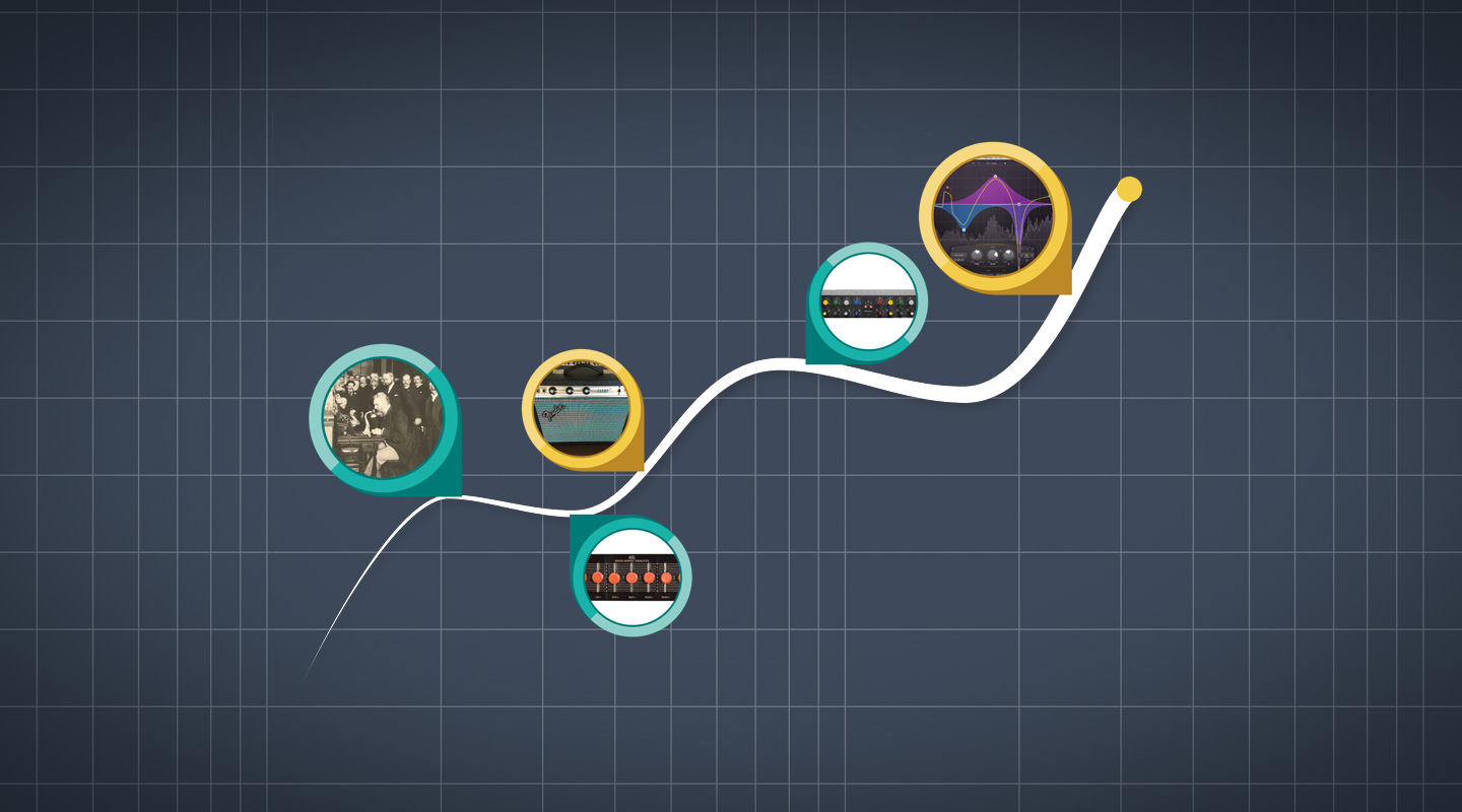
In 1892 Alexander Graham Bell’s telephone system had connected New York to Chicago with a pair of wires over 1400km long. The two parallel wires effectively functioned as capacitor plates, and pretty soon it got up everyone’s nose how the whole thing behaved as a geographically-sized, high-cut filter. To make up for the resultant loss of sibilance and intelligibility, Bell Laboratories developed and installed fixed-frequency, non-adjustable filters to restore the top end, and thus ‘equalise’ all frequencies in the telephone signal.
The first user-adjustable equaliser is credited to John Volkmann from RCA, who created one for movie playback systems in the 1930s. Most picture theatres of the day were built in the silent era, or were converted song and dance venues. The ‘talkies’ brought electronic audio into those venues for the first time. Between the primitive speaker systems, the sound recordings themselves, and the lucky dip of theatre acoustics, it often added up to an unsatisfactory day out for the ticket-paying punter. Volkmann’s gadget offered boost and cut of multiple selectable frequencies, and to theatre managers the altering effect must have seemed almost magical.
At the same time, other companies were developing equalisers to be used in audio production and broadcast. Art Davis of the Cinema Engineering Company hit an early home run by designing the first proper graphic equaliser, the Type 7080. Featuring six bands with 1.5 octave spacing, the unit offered 8dB of boost and cut, zero insertion loss, and faders fashioned from linear 17-position switches sporting ‘typewriter key’ knobs. The unit was an early active device, which employed variable passive filters to alter the cathode resistance of a tube amplifier, and therefore its gain. At the back end there was some make-up gain followed by a push-pull section, driving a transformer that delivered a floating differential output. It was clever stuff for its day. Later, Art Davis defected to Altec, where he designed the seven band Model 9062A graphic equaliser, which remained a benchmark device till the 1970s.
In 1952, Englishman Peter J. Baxandall published his scheme for a negative-feedback tone control circuit using potentiometers as opposed to switches, thus allowing full user control. It also ushered in a new era of fully-active EQ circuitry and became the most reproduced tone control in history. To this day there has scarcely been a hi-fi unit anywhere in the world which fails to incorporate it behind those knobs marked Bass and Treble. Baxandall received no royalties for his invention, but in 1950 the British Sound Recording Association gave him a $25 gold watch, in honour of an earlier version. That watch would be worth something now.
Meanwhile in Texas, Professor Wayne Rudmose had figured out that public address systems needed more than just a bass and treble control to cure feedback. His 1958 paper Equalization of Sound Systems proposed that PA systems could actually be tested for frequency response (using non-existent equipment that would need to be devised), and thereafter filters might be created and installed to equalise that response. His theories were successfully put into practice at Dallas Love Field Airport, and from then on ‘tuning’ a PA became a thing to do.
The next decade saw a lot of work done to further tame PA systems. Rock ’n’ roll was in full bloom, and program material was getting louder. In 1967, Altec Lansing introduced the first 1/3-octave passive notch filter set specifically for PA tuning called the Acousta-Voice system, and from there it was only a hop and a jump to create a 1/3-octave, cut and boost-style graphic equaliser.
The last truly major development in EQ was the parametric equaliser. Historically, graphic equalisers were useful studio tools, but had big faders, and took up lots of space. What engineers craved was a smaller and more flexible device which could be built right into a channel strip. In 1971, Daniel Flickinger invented a sweepable EQ which allowed adjustment of frequency and gain, in three overlapping bands of fixed width. Nowadays, manufacturing a mixing desk without at least one band of sweepable EQ is unthinkable. In 1972, George Massenberg presented a paper on a similar invention that he and two associates had been developing which, besides frequency and gain, allowed user adjustment of the third parameter — bandwidth. Massenberg called his device a ‘Parametric Equalizer’ and he continues to sell them to this day, under the GML brand name.
INDUCTED INTO OBSCURITY
Looking at the work of Massenberg and his contemporaries, one aspect that never gets talked about is how they stood astride a historical line of demarcation for the electrical component called an Inductor. Before Massenberg, if you took the lid off an equaliser you would probably see inductors. After Massenberg, probably not.
Inductors and capacitors are components with electrical properties that vary with frequency, and they are what shapes the response of any frequency or time dependent circuit. They work in equal and opposite ways, so it was always natural to see them together in the same devices, the EMI REDD desk EQ from the ’60s being one fine example.
However, inductors are essentially a coil of wire with properties similar to a radio antenna. In Massenberg’s paper, he described them as marginal performance components which inherently invite parasitic electromagnetic noise into a system, and he proposed the use of several pre-existing electronic Indian rope tricks to do away with them completely. One was an op-amp circuit called a ‘gyrator’, which takes a capacitor and, more or less, draws a moustache and glasses on it to fool the neighbouring electronics into thinking it’s an inductor. The ideas he talked about increasingly appeared in the work of others, and gyrators soon replaced inductors in graphic equalisers. Since then, inductors have become a sad and sorry underclass in audio, and now you only really encounter them inside passive speaker crossovers. If you come across one, loan it a dime.

ALL THINGS BEING EQUAL
(Fig-1) Rudmose used fixed frequency notch filters to equalise the PA in Dallas, and that was that, no knobs. These days fixed EQ is less common, but the RIAA curve has been a solid stayer. On a vinyl record, the grooves wiggle from side to side, and the bass notes (which contain the most energy) wiggle the widest. So in order to fit a useful amount of material on the vinyl the bass is attenuated by 40dB at 20Hz, rising to unity at 20kHz. The filter slope zig-zags between those two points, but what you hear is closer to a straight line. All records are made that way, so a phono input employs a fixed boost filter of the opposite slope, to put everything back to normal.

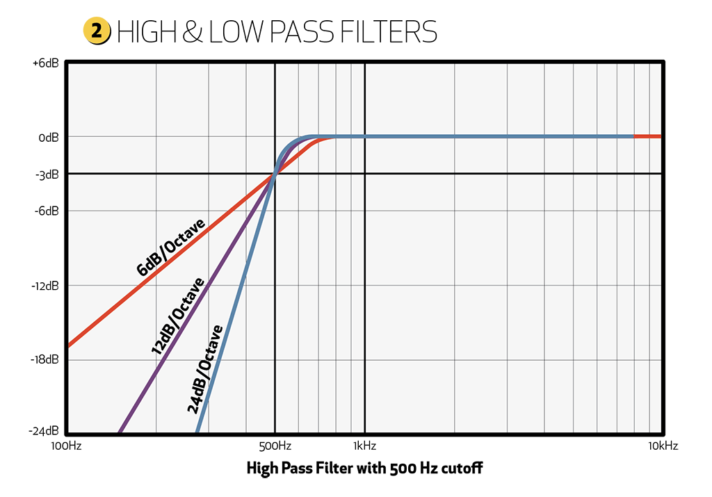
(Fig-2) Most mixing desk channels feature a sweepable or switchable high-pass filter to attenuate sub-bass and proximity issues in microphones. Occasionally you will see a sweepable low-pass filter, to help remove unwanted treble from bass instrument channels. These filters provide a flat response in their pass band, and generally roll off down a 6dB or 12dB per octave slope beyond their cutoff frequency. Filters of a higher order than 12dB per octave are less common, and tend to imply a special purpose. Linkwitz and Riley famously use 24dB per octave filter slopes in their electronic speaker crossovers.

(Fig-3) If you want to affect a specific band of frequencies, you need a bandpass filter. The frequency response is usually bell-shaped, with an upper and lower roll-off slope, and there are two main varieties — Constant Q and Variable Q.
‘Q’ stands for Quality Factor, and is simply the ratio of -3dB bandwidth in Hertz to a centre peak frequency. For example, if we have a centre frequency of 1000Hz with -3dB roll-offs at 414Hz and 2414Hz, then the bandwidth (upper minus lower) equals 2000 Hz, therefore Q=0.5 (1000/2000). For amplitudes less than 3dB there is no -3dB point, and subsequently all kinds of disagreement about how to calculate bandwidth. I don’t want to start a bar room fight, so I will stick with the above as a general principle, and just say that whenever we increase Q, we decrease bandwidth, resulting in sharper curves.
Bandwidth can also be measured in octaves, which are very roughly the inverse of Q — but always slightly more, because they are calculated from either extremity rather than the centre. Since an octave is merely a doubling of frequency, the distance between 414Hz and 2414Hz winds up being about 2.5 octaves.
CONSTANT Q VS VARIABLE Q
When boost or cut is applied to a bandpass filter, bandwidth and Q will either be constant or variable, and the term ‘variable’ does not mean adjustable.

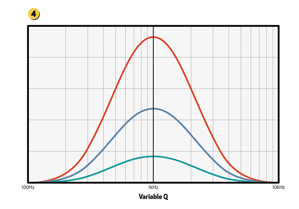
The frequency response curves for a variable Q equaliser (Fig-4) show that the bandwidth or Q of the equaliser changes with the amount of boost or cut used. Sometimes this is called ‘Proportional Q’. At low settings the equaliser exhibits a wider relative bandwidth than at high settings, and only achieves its specified bandwidth at maximum boost or cut, so minor adjustments made at a specified frequency will cause changes to other frequencies some distance away. This type of response is desirable in situations where you want to change the overall tonal balance of a sound, without over-emphasising any particular frequency. Variable Q circuitry is common in old-fashioned tone controls, guitar amps, and most professional equalisers that fail to declare themselves as being ‘Constant Q’.

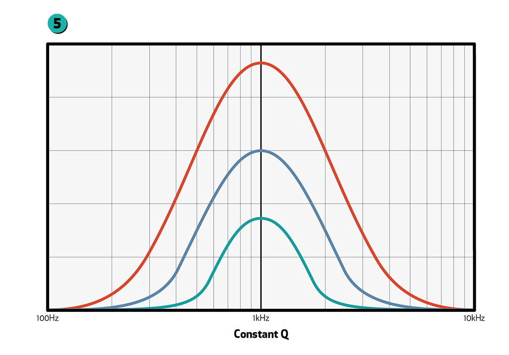
The frequency response curves for a constant Q equaliser (Fig-5) show that, even for small amounts of boost or cut, the equaliser maintains its stated bandwidth. That makes it very useful for applying changes to specific frequencies, in circumstances where you would prefer to leave nearby tones undisturbed. Examples might include removal of feedback, or enhancement of a particular resonance in a musical instrument.
GRAPHIC EQ
In live sound reinforcement, the 31-band graphic equaliser has left its footprint more than any other EQ. With evenly spaced 1/3-octave bands, it gets its name from the way the response curve is so directly displayed (like a graph) by the faders that control it. When you are battling wild frequencies in a pesky room, it’s helpful to quickly see where you’ve been.
Live sound techs talk about their equipment the way a tradesperson talks about their ute. ‘I only nudged the fader, but it produced enough grunt to uproot this tree.’ In that context a good graphic equaliser will be one for which each fader exhibits a solid grasp of its band of frequencies, so that when you move one ‘something happens’ (I have used equipment where nothing happens). Graphic equalisers mainly employ constant Q equalisation, so that bands several faders apart from one other don’t interact, but a superior design will allow bands immediately adjacent to ‘combine’ slightly when the faders are moved together, eliminating any dip that might occur between them. Combining was invented by Art Davis when he created his Acousta-Voice system. He reasoned that if your P.A. is feeding back at a frequency half-way between two adjacent bands, then you will attenuate both, with the expectation that all frequencies between the two ought to be grabbed in the process.
PARAMETRIC EQ
In recording studios, room sound and feedback are not quite as high on the worry list, and EQ tends to be more purely applied to affect the timbre or balance of an instrument. With independent control over bandwidth (Q), frequency and amplitude, a parametric equaliser is able to produce almost any shape of EQ curve one might desire — something the fixed frequency bands of graphic EQ cannot do. Circuits tend to employ a state-variable filter topology using op-amp integrated circuits, and I have never heard of a parametric EQ using valves.
BAXANDALL TONE CONTROL
This classic tone control provides a shelf, as opposed to a peak-type response. A stock standard configuration might produce 15dB cut and boost at 100Hz and 10kHz, with the slopes returning to unity not far either side of 1kHz, but there are countless variations. (Fig-6)

VIRTUAL
In this day and age of software-based recording, there are any number of proprietary algorithms that exist to mimic all of the above, and more. I’m with the peeps who favour minimal EQ and careful mic placement during tracking, though for mixing I will admit to being quite a fan of software equalisers. There are many who love to mix or print through analogue EQ equipment. In the end, if one way sounds better than another, then it is.
EQ PHONE HOME
All that’s useful, of course, but Mrs Tech Bench asked me if there’s a way to manage your woofs and tweets without having to think about it. Well… I tell her about a junior conference technician I knew named Mark. Mark is a genius. On his first real test, he is left alone with a PA and a medical professor on stage, who blathers into his lapel mic about the exciting world of cortico-steroids. Mark thinks he can hear the onset of feedback, but what to do about it? He pulls out his phone and calls his colleague Dave, who is famous for being able to identify any feedback frequency instantly. Mark sings in a whisper down the phone line, ‘Wooooo’. ‘Three Hundred Hertz,’ says Dave. Mark reaches over to the graphic equaliser, pulls down the 300Hz fader, and the problem is gone. ‘Thanks Dave.’
…Now that’s the way to EQ.


RESPONSES