View From the Bench: Amplifier Class Wars
Is Class A the best, or merely the first?
I have consumed too much peyote and am going to die. In my dream haze I see visions of the jungle with its cherry red sky and lemon sun blazing through every fringe. I push a branch aside and step into a clearing where a crowd of people are mingling, shaking hands, and exchanging business cards. Wiping away sweat, I take a heavy box from under my arm and place it carefully on the table in front of me. Inside this box is the best amplifier ever made in the history of everything. It was given to me by an electric serpent at the beginning of time, and I have carried it many miles. Mrs Tech Bench appears at my table and tells me she is there to receive the amplifier. She says she has seen it in her dreams, countless times. Her outstretched hand tempts me with a bushel of cash, but when I reach for it she draws away suspiciously, looks into my eyes, and queries: “Is it Class A?”
“What do you care if it’s Class A?”
“Class A is the best”, she says.
I probe further, “Do you even know what Class A means?”
She stares at me like I am an idiot.
Spurred, I clamber onto my high horse and rant with rising intensity, “Class A is not a badge of achievement. The good amplifiers do not begin at Class A and then descend in quality towards Class Z. Amplifiers are classified in terms of their architecture and operating characteristics, and in that context the term ‘amplifier class’ is interchangeable with ‘amplifier type’. The quality of listening experience one can expect owes much less to the operational class than to the specific design, and it is possible to create good and bad designs in any class. Did you know that some of the crappiest musical greeting cards use Class A amplifiers, and many elite powered studio monitors use Class D. A designer will select an appropriate class based on what their amplifier is trying to achieve…”
By the time I draw breath, Mrs Tech Bench has transformed into Aphasia, the wombat spirit, and burrowed deep into the jungle floor where she can no longer hear my racket. I’ve lost the sale.
CLASS A
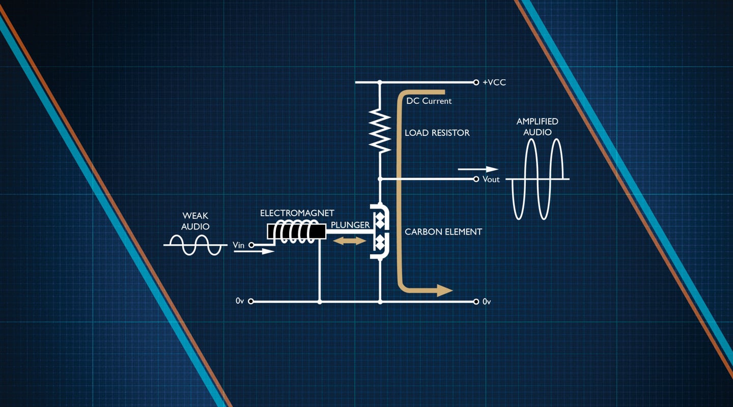
So what is Class A, if not the zenith of all classes? Well, it is merely the oldest. Before transistors there were valves, and before valves there were mechanical carbon amplifiers —[diagram-1] connected in Class A. Diagram shows a scheme for telephone line repeaters, used by Bell Telephone as far back as 1901.

In a Class A amplifier the output transistor (or valve, or carbon element) is turned on all the time, even when no signal is present. This allows an audio wiggle at the input to enjoy continuous attention as the internal electronics follow along without interruption. Pretty much all other amplifier classes chop signals into bits that get processed separately and then re-assembled, which invites glitches. When dealing with very small signals like those from a microphone, it stands to reason that chopping one to bits and then making it 1000 times bigger might risk amplifying the glitches as well. That’s not a problem for Class A, since the signal is processed whole. This is considered its principal advantage. In fact, I don’t believe I’ve come across any small-signal audio input that was not configured in Class A. However, the acts of driving line outputs and speaker loads are now dominated by more recent audio classes.
The conceit with Class A is that since the signal is not interrupted, the output should be a linear recreation of the input, and it generally is, more or less. In fact, Class A’s harmonic distortion performance can be hard to beat.
The concept of ‘linearity’ is worth explaining. If say the signal at your amplifier’s input doubles in amplitude, then the output does likewise. Given a further 20% increase, and the output follows exactly. This behaviour is said to be ‘linear’ because the input and output signals wind up the same shape, with one simply bigger than the other. Now imagine if the input amplitude doubles, but the output only increases by 97%. Then it doubles again but this time the output only increases by 70%. This uneven transfer of signal trace from input to output is said to be ‘non-linear’. It is important to understand that in the above examples we are not just talking about when the music gets louder or softer; we are talking about the rise and fall of every cycle within the audio wave, and the resultant mismatch is called ‘harmonic distortion’.

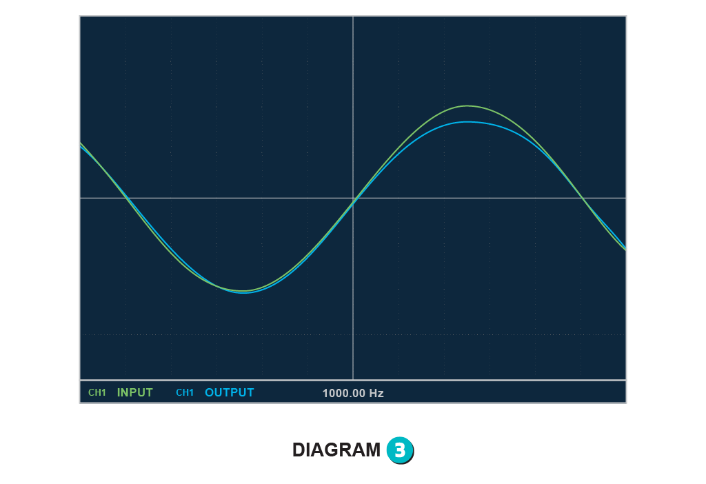
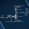
Transistors, valves and carbon elements exhibit good linearity only within a portion of their overall operational range, and beyond that, amplification can be a little wobbly or compressed; sometimes on purpose. In the Fairchild 670 compressor, gain reduction is produced by moving the valves into electronic non-linearity. Circuit architecture itself can offer challenges. In its purest form, Class A is inherently lopsided, with output peaks pulled in one direction by a powerful transistor or valve, and in the other direction by a passive resistor at the mercy of downstream loads [diagram-2] When things get extreme, the result can be a lopsided signal like in this oscilloscope shot of a ‘corrupted-for-the-purpose’ Class A transistor amp. [diagram-3] The signals in and out are overlaid on each other to show their difference, and the mismatch corresponds to about 10% harmonic distortion.

In some old-time Class A valve amplifiers, asymmetrical harmonic distortion is more common than you might think, and since curvy distortion contains lots of even harmonics, it actually doesn’t sound that bad. In fact, it may be the thing we love best about some of that equipment. Other classes tend to distort more edgy and square, which can sound less pleasant, unless you’re a fan of German metal.
Class A has the advantage of only needing a single power supply, but the main drawback is massive inefficiency. Because the active devices are always conducting, and never turn off, most energy winds up dissipated as heat and only a small part drives the signal — typically around 30% or so. In an effort to achieve more efficiency, less heat, and better symmetry, old-time designers went back to their drawing-boards. One idea was to connect two Class A amplifiers in an opposing ‘push-pull’ arrangement, which we today refer to as ‘bridge mode’. Another was to use an active device called a ‘current-source’ in place of the load resistor. Both these techniques deliver superior harmonic fidelity, with the push-pull idea providing near perfect symmetry.
CLASS B
The logical next step was to design push-pull symmetry into a single amplifier. Initially appearing around 1930 (using valves), Class B dispenses with the load resistor, and employs two opposing transistors at its output — one pulls down and the other pulls up (maybe they should be called ‘pull-pull’ instead). [diagram-4]

Each transistor only conducts for half the signal cycle, and both devices are turned off when there is none, so the result is greater efficiency (around 50%) and less heat. The major drawback with Class B is that every time the signal crosses zero, both transistors are completely off, so part of the signal goes missing. This is called ‘crossover distortion’, and it has nothing to do with speaker crossovers. It takes the form of persistent square clipping right in the middle of the signal (rather than at the peaks) and it makes Class B a very lo-fi animal indeed.
CLASS AB
The solution to Class B crossover distortion is to doctor the circuit slightly so that instead of both transistors being turned off during zero-crossings, they are both turned on. That means one device handles the upper half of the wave, both devices work together across the middle, and the other device handles the lower half of the wave. Kind of like a baton being passed in a relay. Thus none of the signal is dropped, and extremely low harmonic distortion figures are possible. Since both transistors are now engaged for slightly longer than half of each cycle, they are said to be biased towards Class A, so this topology gets referred to as Class AB. [diagram-5]

The low output impedance and excellent symmetry of Class AB makes it perfect for driving speakers, transformers and line outputs, so eventually it turned up in everything, and is arguably the most ubiquitous amplifier architecture of the last 50 years. Go back to say 1985, and almost every hi-fi amp, professional sound reinforcement amp, mixing desk, radio, telephone, and audio op-amp was configured in Class AB. Even the Urei 1176 Compressor, revered for its Class A-ness, uses a Class AB stage to drive the output transformer. On the downside, both Class B and AB normally require a second power supply rail, which adds some extra cost and clutter.
CLASS C
Class C amplifiers operate at radio frequencies, and are not used for audio at all. The architecture looks a bit like Class A, but with the output resistor swapped for a tuned circuit usually made up of a capacitor and an inductor. [diagram-6] Class C will amplify a specific frequency while attenuating all others, so it is commonly found in radio transmitters and receivers, and also forms the basis of some oscillator circuits used for logic clocks and digital timing.

CLASS D
The 50% practical efficiency of Class AB seemed like plenty, until the advent of cell phones and mobile music playback systems in the ’80s and ’90s. Batteries cost money, and rechargeables drain quickly (even now) so designers inevitably shifted their focus to power conservation, with the goal of 100% efficiency as their target — meaning every electron consumed by an amplifier would be used to drive headphones or speakers, with zero left over to dissipate as heat. Looked at another way, if efficiency increases from 50% to 100% then your battery will last twice as long, and everyone with a smart phone wants that. Class D (first mooted in 1958) today boasts efficiencies of well over 90% and has revolutionised audio amplifier design. Sorry, the ‘D’ does not stand for ‘Digital’ — Class D does its business in analogue, but goes about it in a non-linear way, a bit like a switch-mode power supply.
Class D uses output switching to rapidly turn transistors (usually MOSFETs) completely on and off. This switching happens at a rate much higher than audio frequencies, so that each switching cycle (called a ‘duty cycle’) handles a very small section of the signal waveform. At a rate of say 200kHz, a 20kHz sine wave would be split into 10 equal sections, and a 20Hz sine wave into 10,000. When switched on, the transistors cause the output voltage to rise by supplying current (via a low-pass filter) to a loudspeaker or other load. A comparison circuit monitors this rise, and when the output gets to the right level (microseconds later) the transistor turns off and waits for the next switching cycle where the process repeats. In my diagram, the input signal is compared to a continuous sawtooth wave whose frequency sets the duty cycle rate. [diagram-7] Because the ‘pulse’ duration within each duty cycle varies according to demand, this kind of energy delivery is known as ‘pulse-width modulation’.

In an alternative variant of Class D the pulse duration is fixed, but the length of the duty cycle varies, and this scheme is called ‘pulse-density modulation’. What both schemes have in common is that they spit tiny pellets of energy at a load, to build mountains of amplitude – a bit like a 3D printer making an object out of droplets of plastic. Because the transistors are only ever turned on for the amount of time required to produce each droplet, there is very little wasted energy, and very little heat, meaning amplifiers can be made smaller because they don’t need a great big ventilation system.
In the late nineties and early noughties, Class D schemes really came of age, making self-powered monitors practical, achievable, and affordable. In pro sound reinforcement these boxes were welcomed with open arms, so much so that it is now unusual to rig a live show without them. Also, Class D amplifiers are used in many current brands of near-field studio monitors, with good ones boasting less than 0.01% Total Harmonic Distortion. In smart phones and other headphone-driving, battery-powered gadgets, Class D is a popular inclusion for its low power consumption, small size, and cool running.
CLASSES E & F
Now we’re back to radio frequencies. Class E is like a mash-up between the tuned linear circuit of Class C and the full on/off switching of Class D. They are designed to be used above 100MHz, where Class C starts to struggle. Class F is like E with fries.
CLASS G
This variant of Class AB was borrowed from some hi-fi amps like the NAD 3220 from 1989, and used to great effect in mobile phones. The basic principle is to use two separate sets of power supply rails — some lower voltage ones for the vast bulk of audio demands, and higher ones rigged to suddenly switch on only for louder peaks and head-banging. Since the higher voltage rails are completely off most of the time, the dividend is lower power consumption, less heat, and longer battery life. [diagram-8]

CLASS H
Used in some cell phones, this scheme takes the idea of Class G to the logical limit. Instead of rail switching, Class H tracks the input signal and moves a single set of power rails up and down in unison. This leads to around 80% efficiency, which is better than Classes G and AB, but not quite as good as D.
CLASS I
A push-pull variation of Class D, patented by Crown Amplifiers, using separate pulse-width modulation on two opposing switches. When the state of both switches match, they cancel each other and there is no output — but when the pulse-width on one is wider than the other, the output will swing towards it. Crown say this is more efficient than regular push-pull versions of Class D, and solves the problem of output transistors blowing up if they accidentally turn on at the same time.
CLASS S
Another version of Class D that is usually associated with radio frequency or digital input audio operation. It applies a fancy algorithm to convert multi-bit digital signals directly into pulse-width modulation, bypassing the normal D-to-A stage. Annoyingly out of sequence, the ‘S’ is generally believed to stand for ‘Switching’.
CLASS T
Yet another glorified version of Class D, in a proprietary design by a company called Tripath — hence Class ‘T’ — from 1996. Apple used them in the G4 and iMac. Their central claim was that a superior process was employed to control the pulse-width modulation, with feedback taken from the switching stage rather than the output, resulting in higher gain, and lower distortion.
ALL CLASS
This writer is not aware of any other meaningful amplifier classes, so most of the alphabet is still up for grabs, if you have any brain-waves. Not sure about the Tripath idea of simply co-opting any letter you like. Will this lead to Meyer, M-Audio, Motorola and Marshall all in litigation over Class M? Hmmm…


RESPONSES