
Microphones: Levels & Gain
In the tenth installment of this series, Greg Simmons mete(r)s out some level-headed advice while providing a brief history of microphone preamplifier design…
In the previous installment we explored the differences between analogue and digital audio equipment, and looked at the industry standards that exist for signal levels within each technology: the NOL of an analogue system, and the Alignment Level of a digital system. We also looked at numerous ways audio signals can be measured and metered, the history behind some long-held misunderstandings about signal levels in digital systems, and some industry standards for setting levels.
It would be easy to think we’ve drifted a long way off-topic from microphones, but the whole purpose of that exploration was to get a better understanding of the signal levels we should be aiming for and why. This, in turn, helps us when setting the gain for our microphones, and that helps us choose a microphone with the appropriate Sensitivity. This installment picks up where the previous installment left off…
LEVEL BEST
A number of metering guidelines and recommendations were discussed in the previous installment. Most of them came from broadcasters and others who deal with dialogue and/or audio content that has already been mixed, mastered and otherwise processed for distribution, transmission and/or streaming.
In his book ‘Mastering Audio’ Bob Katz elaborates on his K-Metering system as described here, which also provides level recommendations for mixing and mastering audio for different mediums. The K-Metering system is designed to be used in conjunction with a standardised monitoring loudness, which makes a lot of sense. It’s interesting reading and includes a detailed history of the VU meter, its intentions and its inadequacies. (The relationships between metering, monitoring and loudness is something we’ll be looking at in a later installment.)
Also, at the time of this writing, the AES (Audio Engineering Society) released their latest level recommendations for Audio Streaming and On-Demand distribution, which can be seen here.
CAPTURING RAW AUDIO
With the exception of RP-155’s Alignment Level of -20dBFS, all of the audio level recommendations mentioned so far apply to finished mixes and mastering – but not for capturing raw audio. However, by using RP-155 and reflecting on the forgotten benefits of the VU meter, we can define some recommendations for capturing close-miked musical instruments and other sources when using the Peak metering available on our digital equipment, as shown below.

Before going any further, please note that these are recommended levels for capturing individual channels or tracks that are ultimately going to be processed and mixed together, and they apply primarily to popular music genres that have relatively small dynamic range requirements. Not only will these level recommendations bring your digital audio signals into a better operating zone, they’ll streamline the mixing process and will be greatly appreciated if you’re capturing or preparing something for someone else to mix – as we’ll see in the next installment.
[For capturing music with greater dynamic range expectations (orchestral, chamber, acoustic jazz, etc.) you might want to lower the centre of the target zone to -24dBFS and broaden the optimum area to extend from -12dBFS to -36dBFS – especially if capturing live performances. We’ll look at these scenarios in the ‘Gain Bending’ installment.]
Target Zone
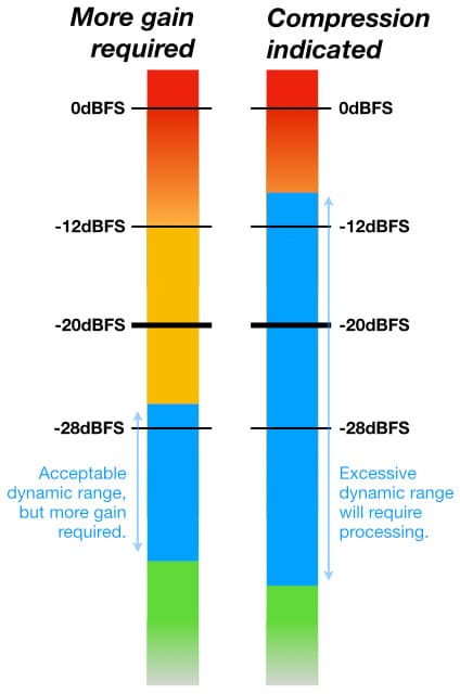
The illustration above shows an optimum Target Zone of 16dB between -12dBFS and -28dBFS, which offers 8dB either side of the RP-155 recommended Alignment Level of -20dBFS. The goal is to keep the signal’s Average or RMS level sitting somewhere around -20dBFS while keeping its highest and lowest Peak levels within the Target Zone whenever possible.
If you don’t have access to Average or RMS metering, aim to keep the note-to-note Peak levels sitting within the Target Zone while also remaining within the space above -20dBFS – which should help to keep the Average level useful. Let’s say you had a signal with 8dB difference between the Peak levels of its loudest and softest notes. It is better for that 8dB difference to exist between -12dBFS and -20dBFS than between -20dBFS and -28dBFS, because this has a more likely chance of keeping the Average level closer to -20dBFS (although that depends largely on the signal’s Crest Factor, as explained in the previous installment).
In the following illustrations the blue section represents the difference between the signal’s highest Peak level and its lowest Peak level.
The goal is to keep the signal’s Average or RMS level sitting somewhere around -20dBFS…

Safety Margin
The area above -12dBFS is a Safety Margin for occasional and unexpectedly high peaks, and is roughly equivalent to the point above the analogue NOL where even the most generously calibrated analogue tape recorders would’ve entered saturation. It’s okay for the signal’s Peak level to go into this area from time to time. Percussive sounds with hard attacks, such as wood blocks and ‘80s kick drums with click pads, will regularly enter this area. Aim to keep their Peak levels below -6dBFS and make sure they stay clear of 0dBFS.
Problematic
Signals with Peak levels that sit mostly in the Problematic area but sometimes venture into the Target Zone need more gain, either in capture or downstream (clip gain, a gain plug-in, etc.) to make them audible against sounds that sit comfortably within the Target Zone.
Signals that sit mostly in the Problematic area but occasionally venture beyond the Target Zone into the Safety Margin will almost certainly require dynamic range control (compression/limiting) and/or automation to keep them audible alongside signals that sit comfortably in the Target Zone.
Application
These level recommendations should be simple to implement with any DAW or digital mixing console. Situations where they’re not easy to implement indicate that the signal might require dynamic processing (compression, limiting, automation) and/or filtering to sit comfortably alongside other signals in the mix. In these situations the best approach is to use a lower gain to ensure the signal does not clip but still delivers a useful signal for further processing and mixing. As Rupert Neve advised many years ago, “a good engineer will not let his signal clip more than once a year”.
AN ATTENUATED HISTORY OF GAIN
Throughout this series references have been made to choosing a microphone with appropriate Sensitivity to place its output level somewhere within the preamplifier’s ‘Goldilocks Zone’ – an area around the gain dial where the gain has not been turned up so high that it’s introducing excessive noise when using passive microphones, but is not turned down so low that even at minimum gain there’s a risk of overloading the circuitry and clipping the signal when using active microphones. If we know the sound’s SPL, the Target Level and the upper and lower limits of the Goldilocks Zone, we should be able to choose the right microphone Sensitivity for the job. To determine some valid upper and lower limits of the Goldilocks Zone we have to start with a quick look at some typical preamplifier designs, at least conceptually…
Preamplification Goals
The traditional microphone preamplifier requires a low noise input circuit with a relatively high impedance (typically 1500 ohms or more) that’s capable of taking the very small signal from the microphone and amplifying it up to Line Level, a job that requires considerable amounts of gain – possibly +70dB (x3162) or more for a vintage ribbon, depending on the SPL of the sound source. Making a low noise preamplifier circuit with a high input impedance input and +70dB of variable gain is difficult to do while maintaining stability, and even harder when the entire circuit has to be small enough to fit into the top of a channel strip on a mixing console. Amplifiers like that prefer to be oscillators…
In 1840 the American humorist Seba Smith (1792-1868) famously wrote “There are more ways than one to skin a cat”, a phrase that’s currently outlived him by over 150 years. The same applies to microphone preamplifiers: there are more ways than one to solve the low noise/high gain/stability problem when amplifying a microphone signal, and nobody really cares how you do it as long as it works and sounds good. Here are some examples…
Transformer
One solution is to share the total gain requirement over two lower gain amplifying circuits, or ‘stages’, as shown below.
Amplifiers like that prefer to be oscillators…
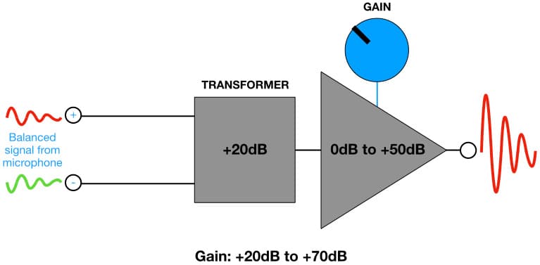
This example uses a transformer as the first gain stage. The transformer is an excellent choice for this application because it provides a differential balanced input with voltage gain and a high Common Mode Rejection Ratio (CMRR) – which is exactly what we need to take the signal from a microphone’s balanced output via a microphone cable. Typically, transformers used for this application are ‘step-up’ transformers with turns ratios between 1:5 and 1:10, which translates to voltage gains from +14dB (x5) to +20dB (x10). The transformer in the illustration above has a turns ratio of 1:10, which gives it a voltage gain of +20dB. It’s followed by a second stage with variable gain from 0dB (x1) to +50dB (x316.2), making the total gain range +20dB to +70dB (x10 to x3162).
One problem with this design approach is that the voltage gain of the transformer determines the minimum gain possible, which can be too high for some situations. Also, in some smaller and/or lower cost transformer designs a high peak level from the microphone can cause transformer saturation – a form of magnetic clipping that’s akin to tape saturation and, similarly, treads a fine line between euphonic and useless.
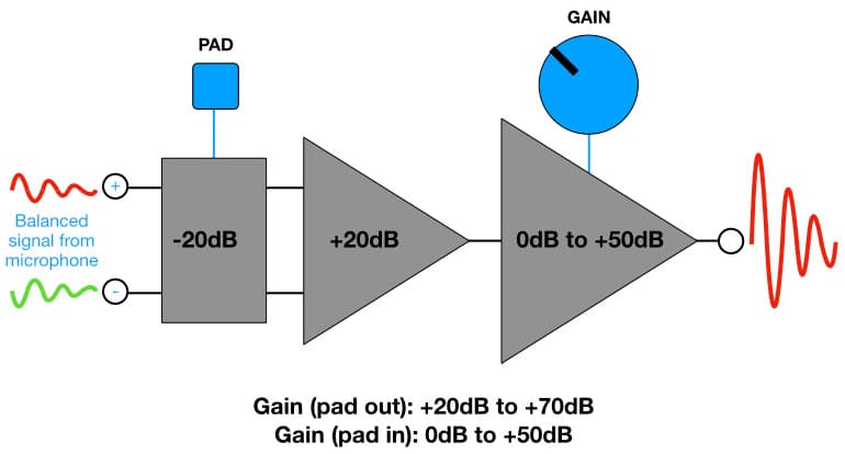
With or without saturation, a high peak level going into a step-up transformer means an even higher peak level coming out of it that can overload the variable gain stage and/or other circuits further downstream, resulting in clipping distortion. The signal coming out of the preamplifier is too high even with the gain turned all the way down to minimum, which, in this example, is the transformer’s voltage gain of +20dB. This problem is solved by adding a switchable -20dB (÷10) pad to the input, as shown below:

The pad could be inserted before or after the transformer; for the purposes of the illustration we’ll put it before. The result is a preamplifier with variable gain from 0dB to +70dB (0dB to +50dB with the pad, and +20dB to +70dB without the pad). Add phantom power and a high pass filter and you’ve got a versatile ‘take on anything’ microphone preamplifier similar to those seen in professional mixing consoles ever since Neumann invented phantom power in the mid ‘60s.
Transformerless
In the late ‘70s there was a move away from transformers. This saved considerable space on each channel strip (allowing more channels in the same space), while reducing the cost per channel, improving some specifications and worsening others – although, of course, the marketeers focused on the improvements only. The early ‘transformerless’ preamplifier designs essentially replaced the transformer with an electronic circuit, as shown below:
Numerous circuits were designed to emulate and replace the transformer in this application, or even to create an entirely new microphone preamplifier design using transistors throughout rather than transformers. These were often packaged as small circuit-board-in-a-box designs containing discrete components potted in resin with terminals ready to mount directly onto the circuit board of a mixing console’s channel strip, rather like a giant chip. Some were ultimately built into chips. These included products from Analog Devices, John Hardy Company, Benchmark Media, Harrison, Valley People and Philips.
Padless
With the advent of the home studio and the project studio came the need for a preamplifier that was cheaper to make and simpler to use. It didn’t need the 0dB to +70dB gain range of the professional consoles because the intended market was recording musicians using dynamic and condenser microphones to close-mic drums, guitars and vocals at home. [Royer had not yet resurrected the ribbon microphone as a viable option, so there was no need for high gain/low noise preamplifiers.] This lead to the ‘padless preamplifier’, which is now commonly found on most affordable mixing consoles and interfaces.
The illustration below shows a padless version of the preamplifier shown earlier. The gain range is variable from +10dB to +60dB, which is sufficient for most close-miking applications using condenser and dynamic microphones when recording popular music genres. As an added benefit there is no pad switch for the non-technical user to misunderstand and misuse, which solved an on-going problem for the after-sales support people: no more angry calls from technically-illiterate users saying “the preamplifier is too noisy” or “the preamplifier doesn’t have enough gain” when the real problem was that the pad was switched on when it was not needed, and no more angry calls saying “the preamplifier keeps distorting” when the real problem was that the pad was not switched on when it was needed.
Using the pad switch when it is not needed means unnecessarily more preamplifier gain is required, which can result in unnecessarily noisier signals. Conversely, not using the pad switch when it is needed allows signal peaks to go higher than necessary, increasing the risk of clipping distortion. The padless preamplifier’s ‘happy medium’ gain range of +10dB to +60dB simplifies the circuit and reduces costs, but with the trade-off of lower versatility.

If the minimum gain of +10dB is too much you’re going to need a pad; either one that’s built in to the microphone, or an external pad like the simple circuit shown at the end of this installment…
Discrete & Class A
When a preamplifier or other audio circuit is described as ‘discrete’ it means it is made from individual electronic components (resistors, capacitors, transistors, etc.) rather than integrated circuits aka ‘chips’. In a discrete circuit the designer can select and hand-match electronic components to minimise noise, and can also use higher voltage power supplies than chips allow, which, in turn, translates to greater Headroom (among other things).
You will often see the term ‘discrete’ used alongside the term ‘Class A’, referring to a circuit design that amplifies the entire waveform with one amplifying stage – as opposed to splitting the signal into positive and negative half-cycles that are amplified individually and then joined back together (Class B), which can result in crossover distortion due to tiny level mismatches between the half-cycles when they are re-connected. Class A is often considered the most pure form of amplification, but it is also the least efficient. Efficiency is important when working with low-powered devices (e.g. bus-powered interfaces) and with amplifier chips where low efficiency means more heat and therefore more thermal noise and increased risk of component failure. Most of the chips used for amplification use ‘Class AB’, which uses Class A when signal levels are small and crossover distortion will be significant, but switches to the more efficient Class B when signal levels are high and crossover distortion will be insignificant.
Preamp-On-A-Chip
Contemporary preamplifier designs – especially those found in interfaces – often use the ‘preamp-on-a-chip’ designs from manufacturers such as Burr-Brown, THAT Corporation, Analog Devices and others. These put all of the important components of a microphone preamplifier circuit into a single chip and allow the manufacturer to customise some performance characteristics with the use of external electronic components. You will often see the same preamp-on-a-chip inside a budget interface and an expensive interface, but they’ll offer different levels of performance due to how the manufacturer has configured the external circuitry and the quality of the AD converter they’re following it with.
In products where the preamp-on-a-chip’s output goes directly into an AD converter within the same device (e.g. an interface or a digital mixing console), some interesting design possibilities arise. Because the output of the preamplifier is going directly into the AD converter and does not need to be made available to the user as an analogue signal at that point, there is no need for the preamplifier or the AD converter to conform to the +4dBu industry standard NOL. This means the preamplifier and AD converter can be designed to run with lower power supply voltages (e.g. bus powering) and lower NOLs, and the preamplifier chip only needs enough gain to bring the microphone signal up to the required level to drive the AD converter chip. It also means the total gain can be shared between the preamplifier and the AD converter; in this situation the preamplifier’s maximum gain only needs to be enough to get the signal sufficiently above the AD converter’s noise floor. The rest of the gain is provided by DSP, raising the level of the preamplified signal along with any noise it contains and any noise present in the AD converter’s analogue input circuit.
You will often see the same preamp-on-a-chip inside a budget interface and an expensive interface…
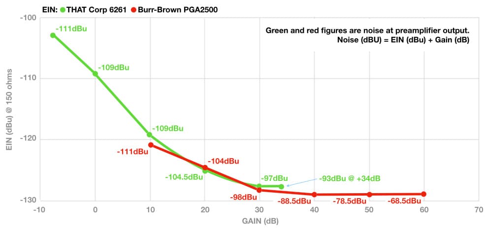
The illustration above shows the EIN curves for Burr-Brown’s long-established PGA2500 (red) as used in interfaces from Apogee and Antelope to RME and Universal Audio, and THAT Corp’s very recent 6261 (green). The PGA2500 has digitally-controlled gain that’s variable in 1dB steps from +10dB to +60dB, giving it a range of 50dB. The 6261 also offers digitally-controlled gain in 1dB steps from -8dB (attenuation) to +34dB, giving it a range of 42dB.
The illustration below is from the data sheet for THAT Corporation’s 6261 preamp-on-a-chip; note that the digitally-controlled gain is shared between the preamplifier and the ADC driver (a circuit designed to provide a signal to the AD converter). Conceptually, it can be viewed as a modern-day return to the two-gain-stage approach except now both stages have variable gain. Also note that the output of the ADC driver is rated at 2VRMS for Full Scale (0dBFS), which puts the -20dBFS Alignment Level at 0.2VRMS rather than the 1.228VRMS required to meet the industry-standard Alignment Level of-20dBFS (which is aligned to +4dBu). It’s 15.8dB lower than +4dBu, and therefore requires 15.8dB less gain to reach its NOL. With that in mind, the maximum gain of +34dB does not seem so low. At the same time, having a minimum gain of -8dB means it can handle a higher input level without the need for a pad.

While the preamp-on-a-chip designs are affordable and offer numerous advantages, they can’t match the performance that’s possible with discrete designs. It’s also worth noting that many of the preamp-on-a-chip designs (such as the PGA2500) offer a minimum gain of around +10dB, similar to the padless preamplifiers described earlier. If the minimum gain of +10dB is too much, see the pad circuit below.
Gain-Ranging
Some field recorders (e.g. Zoom, Sound Devices) offer the ability to record in ‘32-bit float’ format, which provides huge dynamic range – far more than a microphone could ever deliver. To achieve this they use a technique known as ‘gain-ranging’. Instead of using one preamplifier and one AD converter on each microphone input, they use two. One preamplifier/converter combo has a fixed gain that’s optimised for capturing and converting low signal levels, the other has a fixed gain that’s optimised for capturing and converting high signal levels. The outputs of both converters overlap to ensure a smooth transition between them, and the rest is done in DSP to provide a 32-bit floating point signal that is essentially impossible for any contemporary microphone to drive beyond 0dBFS. It’s possible to overdrive the analogue inputs of the preamplifiers if you try hard enough, but that’s unlikely from a microphone output.

Gain-ranging isn’t new — you’ll see it in the AES42 digital microphones from over a decade ago — but it’s making its way into affordable audio devices and de-emphasising the need to focus on getting the gain right from the start. Speaking of which…
TOWARDS GOLDILOCKS
How does all of this information help us to define the Goldilocks Zone? It’s all about choosing a microphone with the right Sensitivity for the sound source and preamplifier so that we can reach the Target Level given in the recommendations above (-20dBFS Average) without introducing more noise than necessary when using low Sensitivity passive microphones, and without risking distortion when using high Sensitivity active microphones.
Next installment we’ll delve into the Goldilocks Zone, define upper and lower limits for gain, and include some practical examples…
SIMPLE EXTERNAL PAD
This simple pad circuit can be built into the shell of an XLR connector and will provide approximately -20dB of attenuation, assuming the microphone has an output impedance of 150 ohms and the preamplifier has an input impedance of 1500 ohms. The amount of attenuation will change slightly with different microphone and preamplifier impedances but a dB or two either side of -20dB is irrelevant when the goal is to reduce the microphone’s signal level enough that you can apply some gain to bring it back to a useful level without clipping.
Use 1% tolerance resistors throughout and make sure the two 680 ohm resistors are matched as closely as possible (in Ohms) to maintain the preamplifier’s CMRR (Common Mode Rejection Ratio). Buy a dozen and use a multimeter to find a pair that have the most similar values; the matching between them is more important than how close each one is to 680 ohms.
The circuit will work with passive microphones but may affect the phantom power for microphones that require it. Anyone who has experienced the problem of overloading a padless preamplifier when close-miking kick or snare with a contemporary dynamic microphone (i.e. a dynamic microphone that uses a neodymium magnet) will appreciate this simple solution.
[For a -10dB pad replace the 680 ohm resistors with 510 ohm resistors, and replace the 160 ohm resistor with a 470 ohm resistor.]







Hi Greg,
Can we link to your articles on social media?
Absolutely. They’re there to share…