
Microphones: Gain Structure
In the twelfth installment of this on-going series, Greg Simmons lays down the rules for setting microphone gain – before telling us how to bend and break them in the next installment…
In the previous three installments we’ve explored the interaction between the sound source’s SPL, the microphone’s Sensitivity and the preamplifier’s gain control, and seen how they relate to our signal’s level, noise and headroom. Along the way we’ve looked at microphone choice and preamplifier choice, and came up with some level recommendations.
In this installment we look at the traditional rules for setting and maintaining gain, partly as a precursor to understanding when and why we might want to bend or break them (as discussed in the next installment). Obviously we need to understand why those rules exist before we attempt to bend or break them, and that means we need to understand the concept of ‘gain structure’. The best way to do that is to look inside the channel strip of a traditional analogue console, but before we do that…
WHAT IS ‘GAIN STRUCTURE’?
It’s a term that often appears in on-line forums and similar audio-related gathering places, usually when someone is describing a problem they’re having with noise or distortion. Typical problems are “The signal is distorting, even when the fader is pulled all the way down” and “The signal is noisy and not loud enough, even when the fader is pushed all the way up.” Invariably someone will authoritatively reply “You’ve got the gain structure wrong” and leave it at that – a response that is simultaneously as valuable and as worthless as a U47 without a power supply.
The term ‘gain structure’ can be used to describe a) the amounts of gain being used throughout an audio signal path, or b) the signal levels throughout an audio signal path. These are ultimately different ways of looking at the same thing, because the amounts of gain determine the signal levels. It’s important to note that the word ‘gain’ is being used in its broadest sense here and applies to anything in the signal path that is capable of increasing or decreasing the signal’s level. In addition to gain controls, this use of the word ‘gain’ includes trim controls, pads and attenuators, in-line boosters, faders, EQ, dynamics processors and so on. If it is capable of changing the signal level it is considered part of the signal path’s ‘gain structure’ or ‘gain equation’…
Every audio signal path has a ‘gain structure’, from a simple interface to a full-blown multitrack studio or PA system. The signal path consists of individual devices or circuits (preamplifier, equaliser, compressor, etc.), each designed to work within a range of signal levels defined by its NOL, its headroom and its noise floor.
When the gain has been correctly structured throughout the signal path it means the levels coming out of one device or circuit will be appropriate for the next device or circuit, and there should be no issues with levels, noise or distortion.
When the gain has been incorrectly structured throughout the signal path it means signal levels will be too low in some places (noise risk), and/or too high in other places (distortion risk). Often, the user inadvertently creates one of these problems in an attempt to fix the other while not understanding the gain structure concept. Hence, “You’ve got the gain structure wrong…”
Ideally each device or circuit would have its own meter so we could keep an eye on the signal levels throughout the signal path, but that’s not always practical or affordable – and it’s not even necessary if we understand the signal path’s gain structure properly. We’ll start at a device level by looking at how different pieces of equipment are connected together to form a complex signal path, in this case a complete multitrack recording studio. Then we’ll zoom in to a circuit level and look at the signal path through a mixing console’s input channel.
THE OLD WAYS, THE TRUE WAYS
At the core of the gain structure concept for analogue audio equipment is the NOL, as discussed in the ninth installment of this series. ‘NOL’ stands for ‘Nominal Operating Level’ and is the level shown as 0dB on a VU meter, otherwise expressed as ‘0dBVU’. On professional analogue audio equipment the NOL of 0dBVU is represented by a 1kHz sine wave with an amplitude of 1.228VRMS, which converts into a signal level of +4dBu. It’s considered low enough to provide sufficient headroom, but high enough to maintain a useful S/N Ratio.
You’ve got the gain structure wrong…
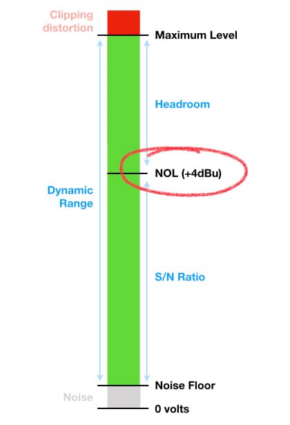
All equipment in the professional analogue audio world is aligned to the same NOL, so that 0dBVU out of one device appears as 0dBVU into another device. In this way, the entire audio system operates as an integrated whole; if you get the level right at the preamplifier it’s also going to be right throughout the rest of the system – unless you intentionally mess it up, as we’ll be doing in the next installment.
The illustration below shows how the standardised NOL of +4dBu works in the professional analogue multitrack recording studio. A metered level of 0dBVU (+4dBu) coming out of the mixing console’s Bus Outputs appears as 0dBVU on the Multitrack Tape Recorder’s meters, and a level of 0dBVU coming out of the Multitrack Tape Recorder appears as 0dBVU at the mixing console’s Tape Inputs. Likewise with the two-track recorder and the effects processors. Everything is aligned to the NOL of 0dBVU, representing a signal level of +4dBu or 1.228VRMS. Furthermore, the studio’s monitor speakers are calibrated so that 0dBVU out of the console’s monitoring section and into the monitor speakers’ power amplifiers produces a known SPL at the monitoring position – which is typically somewhere around 85dB SPL, in accordance with the Equal Loudness Contours to ensure the best tonal translation between different playback levels and to minimise the risk of hearing damage due to long-term exposure.
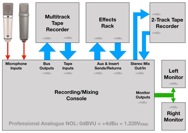
In this multitrack studio situation, where all the individual devices are calibrated to the same NOL of +4dBu, the gain structure throughout the system relies entirely on the engineer setting the gain right at the microphone preamplifier to reach the NOL at the Bus Outputs while also understanding how the use of EQ, insert processing and faders within the mixing console’s channel path and mix buses can affect the signal’s level. Essentially, if the signal coming out of the mixing console’s Bus Output is at the NOL, it should remain at the NOL throughout the signal path – except when it’s being adjusted appropriately to place it in a mix (e.g. a monitor or headphone mix while recording, or a mix to the stereo bus when mixing down).
The NOL concept dates back to the early days of analogue tape, when recording levels needed to be high enough to overcome tape hiss but low enough to provide sufficient headroom. Although it’s an old standard, the audio engineers and equipment designers who established it knew enough about audio and music signals to get it right – which is why the NOL of +4dBu with at least 20dB of headroom remains an industry standard today.
Interestingly, the RP-155 Standard put forth by the Society of Motion Pictures and Television Engineers (SMPTE) recommends that digital audio equipment be aligned so that the analogue NOL of +4dBu at the input of a digital audio device creates a digital level of -20dBFS, again leaving 20dB of headroom. This is known as the digital system’s ‘Alignment Level’ and was discussed in the ninth installment of this series.
When calibrated to an Alignment Level of -20dBFS, digital recording equipment has higher headroom and considerably lower noise than the analogue tape that was in use when the NOL was conceived. That means we can aim for a lower level than -20dBFS when we need more headroom, and a higher level than -20dBFS when we need less noise. That’s what ‘gain bending’ is all about, and we’ll be looking at that in the next installment – before doing that we have to understand the traditional rules for setting gain, so let’s get into that analogue channel strip…
Gain Structure: Channel Strip
The illustration below shows the signal flow through a typical analogue mixing console’s channel strip when it’s configured for recording. The black line through the middle represents the signal path, from left to right. The microphone signal enters the preamplifier at the left side of the illustration, where it is amplified to the NOL. The amplified signal then makes its way to the right side of the illustration via the EQ, the insert point (in some consoles the insert point can be placed before the EQ if desired), the fader, the pan/assign section, and, finally, a Bus Output stage that routes it to the appropriate input of the multitrack recorder. The signal is also directed to the Auxiliary Send system from before and after the fader to provide pre-fade and post-fade sends. Note that the channel strip itself ends at the output of the Pan/Assign section.
…the audio engineers and equipment designers who established it knew enough about audio and music signals to get it right…
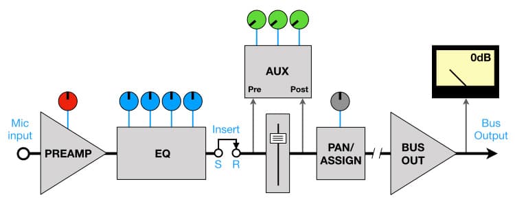
The same signal flow applies to mixing a live performance for sound reinforcement applications except the signal coming out of the channel strip is directed to the stereo mix bus, often via ‘subgroups’ intended to group similar sounds/instruments together. Each subgroup has a master fader for convenient control of grouped sounds, e.g. one fader controls the overall level of the drums, one controls the overall level of the vocals, etc.
Some consoles offer a Direct Out for recording (not shown here). This signal is typically taken directly from the preamplifier, or from immediately before or after the fader (RTFM to find out). Patching the channel’s Direct Out to the input of a multitrack recorder allows the signal to be recorded without going through the additional circuitry of the Bus Output (using the Bus Output is fast and convenient, but it’s really only necessary if mixing two or more channels together to be recorded onto the same track). The insert point’s Send output (S) can also be used as a form of Direct Out, although the signal level at that point is often a few dB below the channel’s NOL.
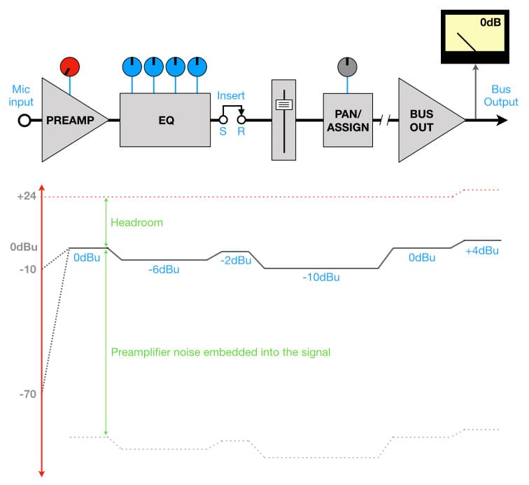
The illustration above is the same channel strip shown earlier, but with the Auxiliary Send section removed to because it’s not part of the signal path we’re currently focused on. Beneath it is a graph showing how the signal level changes as it passes through the individual stages or circuits of the channel strip (black line). This is commonly referred to as a ‘gain structure diagram’, and this one has been drawn to align with the channel strip above it.
The two dotted black lines at the far left show the range of microphone signal levels the preamplifier can work with, in this example from -10dBu to -70dBu. The black line from left to right shows the signal level at each stage of the channel strip when the preamplifier gain has been correctly adjusted so that the level at the Bus Output reaches the NOL of +4dBu. According to the gain structure diagram we’re using, when the Bus Output is at +4dBu the level at the output of the preamplifier will be 0dBu.
The dotted red line across the top shows the maximum signal level the channel strip can reach before clipping (+24dBu), which allows us to see how the headroom changes as the signal passes through the channel strip. Notice that the maximum level rises at the Bus Output? This is to compensate for the +4dB rise in the signal level at the Bus Output and maintain the same headroom, and also because numerous signals may be sent to the same Bus Output (especially if it’s a mix bus) which will increase the overall signal level and therefore require more headroom. [Some analogue mixing consoles were famous for having a lot of headroom on their stereo mixing bus, making them a good choice for mixing. Others were known for having good headroom on the channels but not enough on the mixing buses, making them a good choice for recording/tracking but not for mixing.]
The dotted grey line at the bottom represents the noise from the preamplifier that has been embedded into the signal – note that other sources of noise from the circuitry in the channel strip have not been included here because they’re considerably lower than the microphone and/or preamplifier noise.
Follow The Signal Path
Let’s see how the signal level, headroom and preamplifier noise change as we make our way through the channel strip. For convenience, we’re going to assume the microphone is providing a signal level of -30dBu and has an output impedance of 150 ohms, and that the preamplifier has the same EIN curve we’ve been using throughout this series (shown below).
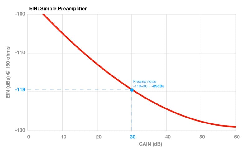
The gain structure diagram shows us that the optimum level at the output of the preamplifier should be 0dBu in order to get +4dBu at the Bus Output; therefore our microphone signal level of -30dBu requires +30dB of gain to reach 0dBu. According to the EIN curve a gain of +30dB results in a noise level of -89dBu out of the preamplifier, which becomes embedded into the audio signal that flows through the channel strip.
Going back to our gain structure diagram and projecting down from the output of the preamplifier we can see that the signal level is 0dBu, the preamplifier noise of -89dBu is 89dB below the signal level of 0dBu, and there is 24dB of headroom.

This channel strip’s circuit is designed so that the signal level drops from 0dBu to -6dBu before entering the EQ circuit, which provides an additional 6dB of headroom in the EQ circuit in case large boosts are required. The preamplifier noise component of the signal drops to -95dBu, and there is 30dB of headroom.
The signal level then rises to -2dBu at the insert point, putting it 6dB below the NOL of +4dBu. It’s not unusual for a console’s insert point to be slightly lower than the NOL. The preamplifier noise is now at -91dBu and there is 26dB of headroom.
After the insert point, the signal level drops significantly to -10dBu before entering the fader, giving room for the user to increase the level by +10dB if necessary (most faders offer +10dB at their maximum setting) without compromising the headroom.
The signal returns to 0dBu after the pan/assign section, and is then amplified to reach +4dBu at the Bus Output to provide the industry-standard NOL.
We can see from the gain structure diagram that if we get the level right at the output of the preamplifier it will be right throughout the channel’s signal path (assuming we’re not applying any EQ or moving the fader away from its 0dB position), and will ultimately give us the industry standard output level of +4dBu.
Although this is a fictitious example with levels chosen specifically to demonstrate how to read a gain structure diagram, it nonetheless shows the importance of getting the preamplifier gain right to begin with. All of the numerous level changes that are designed into the signal path are based on the assumption that there is a known level coming out of the preamplifier (in this example, 0dBu). If we get that level wrong then all of the other levels throughout the channel strip will also be wrong, and we increase the risk of clipping distortion or excessive noise whenever we compensate for a wrong level with another wrong level. In other words, whenever we’ve got the gain structure wrong…
Setting Gain Correctly
Our goal is to set the preamplifier’s gain so that it amplifies the microphone signal up to the appropriate level to provide the NOL at the Bus Output. To do that we need a meter to show us the signal’s level. Some consoles have appropriate metering built into the channel strip, others have a PFL or Solo function that (when invoked) shows the signal’s level on a meter somewhere.
Alternatively, and arguably more relevantly, we can use the metering on the console’s Bus Output (or even the associated input metering of the multitrack recorder if it has been aligned to the Bus Output). In this case, to get an accurate indication of the signal level coming out of the preamplifier we need to make a direct connection between the preamplifier and the Bus Output meter. However, as we’ve seen in the earlier examples about the channel strip’s gain structure, the signal coming out of the preamplifier passes through a number of items before it reaches the Bus Output meter. There is the EQ, the insert point (if anything is inserted), the fader, and the pan/assign section. Each of those items is capable of altering the signal’s level, and collectively they form the channel’s overall ‘gain equation’; if any of these items is altering the signal’s level then the value shown on the meter won’t be an accurate indication of the level coming out of the preamplifier. This will, in turn, cause us to set the gain incorrectly…
If we get that level wrong then all of the other levels throughout the channel strip will also be wrong…
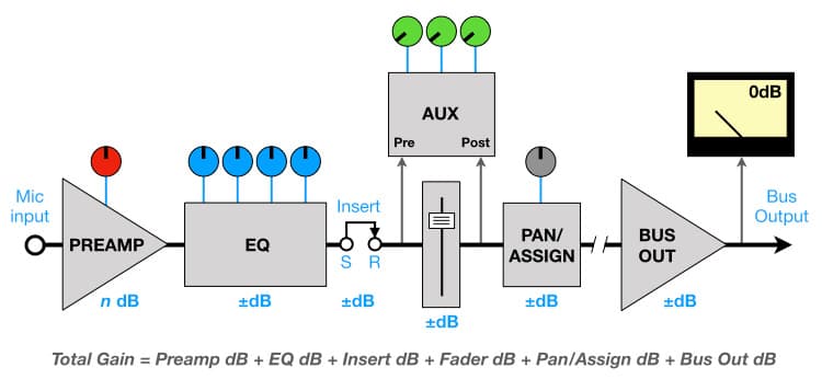
To set the preamplifier’s gain correctly we need to ‘clear the path’ between the preamplifier and the meter; in other words, we need to make sure that nothing in the signal path is altering the signal’s level. From left to right this means:
a) bypassing the EQ (or making sure that all boost/cut controls are set to 0dB);
b) bypassing or removing any processing connected to the insert point (note that on some insert equipment the Output Level control remains in operation even when the processing is bypassed);
c) ensuring the channel fader is set to its 0dB or ‘Unity’ position;
d) switching off the pan control, or panning it hard left or right (typically left for odd numbered buses, right for even numbered buses) in accordance with the facilities and operation of the particular assignment section;
e) if there’s a user-accessible Bus Master or Subgroup master level control or fader, ensure it is set to its 0dB or ‘Unity’ position.
By taking these steps we will establish a direct path from the output of the preamplifier to the Bus Output meter, as shown below. The preamplifier is, conceptually at least, the only source of gain. The level shown on the meter is correct it means the signal level coming out of the preamplifier will also be correct – which allows us to adjust the gain correctly.
This process should be done in a one-channel-per-meter manner to ensure that metered levels are accurate. If there are two or more sounds being mixed together and going to the same track and meter (e.g. bass guitar direct and bass guitar amp mic) the gain should be set for each channel individually, and then the balance between the two sounds and the resulting overall level determined by their individual channel faders while ensuring the combined level does not exceed the NOL at the Bus Output.

The procedure above takes everything out of the channel’s gain equation except for the preamplifier, ensuring that every channel begins with the correct amount of gain at the preamplifier. Individual channels can then be processed as desired and any changes in the signal level after processing can be compensated for appropriately – bearing in mind that each stage of the channel path (EQ, inserted processor, fader) is essentially another gain control that affects the signal level coming out of the channel, and remembering that the preamplifier’s gain was initially correct before any additional processing was applied.
PFLing
If you’re using a PFL meter to check signal levels then things get a bit easier. ‘PFL’ stands for ‘Pre-Fader Level’ and/or ‘Pre-Fader Listen’. It’s mostly a feature on mixing consoles designed for live sound reinforcement, in which case it routes the signal from before the fader (hence, ‘Pre-Fader’) to the headphone socket for the ‘Listen’ and to a meter for the ‘Level’. Because it’s taking the signal from before the fader we don’t have to worry about the settings on the fader or anything after it (Assign Section, SubgroupMaster, Mix Master). However, we need to be aware of where the PFL function is taking the pre-fader signal from within the channel strip. If the signal is being taken immediately after the preamplifier then we can rely on it to set gain. If the signal is being taken from immediately before the fader – after the EQ and insert point – then we need to consider the influence of the EQ and any processing connected to the insert point.
Soloing
Instead of PFL, mixing consoles designed for studio work have a ‘Solo’ function on every channel strip. Pressing the Solo button mutes all other channels going to the mix so that only the Solo’d channel is heard through the monitors and seen on the meters. [Consoles designed for live sound reinforcement obviously shouldn’t have a Solo function: you don’t want to invoke a Solo function in the middle of a live mix unless you plan on being promptly and disgracefully retired.]
Because the Solo’d channel signal is the only signal going to the meters, all the information described here regarding setting gain and compensating for EQ and insert processing still applies – although you also need to be aware of what type of Solo function is on offer. Some consoles take the Solo’d signal from immediately before the channel strip’s pan/assign section, which means it is heard in mono and the level you’re seeing might not reflect any additional changes in level caused by the pan control. Others offer what’s called ‘Solo-In-Place’, which takes the Solo’d signal from after the pan control so it is heard in the correct position in the stereo image (hence ‘in place’) and the metered level should show the effect of the pan control. If you’re in doubt about the type of Solo function your console or DAW offers, RTFM (i.e. consult the Owner’s Manual because that’s why they wrote it).
Getting It Worng Wrong
What are the consequences if we get it wrong? Let’s say the channel’s fader was accidentally sitting at -12dB while setting gain, as shown in the illustration below. This will reduce the level of the signal coming out of the fader by 12dB, causing the level shown on the meter to be 12dB lower than it should be. This will, in turn, mislead us to add 12dB more gain to the preamplifier than is necessary to reach the desired level on the meter. The signal coming out of the preamplifier is now 12dB higher than it should be, losing 12dB of headroom through the EQ and insert point. There’s a high risk of clipping as the signal passes through the EQ or insert device, and no amount of fader tweaking will fix that because it’s happening before the fader. There’s also the risk that any inserted processing (compression, limiting, etc.) will be driven 12dB harder than it was designed for – which means it could be slamming into high levels of gain reduction even at minimal threshold or input settings.
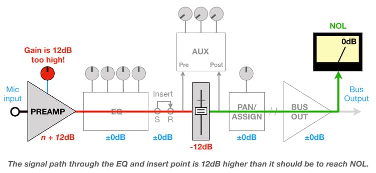
The solution to the above problem is, of course, to return the fader to its 0dB position and re-adjust the gain. It’s a good example of the interaction between the different items in the signal path.
In essence, we can think of the channel strip as having two points where we can intentionally alter the signal’s overall level: the preamplifier gain at the beginning, and the fader at the end. Which one we use depends on what’s happening in between them (i.e. at the EQ stage and the insert point). Let’s look at some examples of how to compensate for changes in overall signal level after applying EQ or other processing, assuming that in each case the level was sitting comfortably at the NOL before the processing was applied. It’s all about preserving headroom throughout the channel strip, because a dB or two more noise is preferable to a clipped signal.
Compensating For EQ
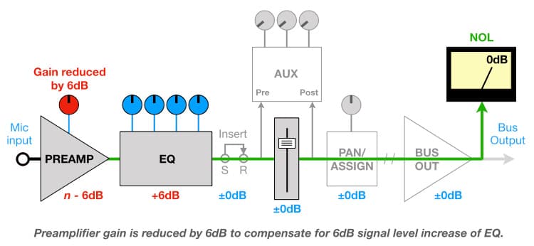
After applying EQ, if the signal’s metered level is higher than the NOL it means the combination of boosts and cuts used in the EQ are ultimately increasing the overall signal level. The total gain before the fader is now the gain of the preamplifier plus the gain of the EQ, and we should compensate by reducing the preamplifier’s gain to preserve headroom going into the EQ and throughout the signal path.
For example, if the metered level after applying EQ is 6dB higher than it was before applying EQ, we should reduce the preamplifier gain by 6dB to bring the overall level back to the NOL while preserving headroom. Reducing the fader by 6dB will also return the overall level back to the NOL, but it will not preserve headroom in the EQ stage, at the insert point or as it enters the fader circuit.
Conversely, if the signal’s metered level is lower than the NOL after applying EQ, it means the combination of boosts and cuts used in the EQ are ultimately reducing the overall signal level; i.e. the EQ is applying attenuation. The total gain before the fader is now the gain of the preamplifier minus the loss of the EQ. In this case we need to compensate by increasing the fader level. Why? Because we know that the preamplifier’s gain was already at the right level before applying the EQ, and increasing the preamplifier’s gain further (to compensate for the following loss in the EQ) reduces headroom coming out of the preamplifier and into the EQ, increasing the risk of overloading the input of the EQ circuit.
For example, if the metered level after applying EQ is 6dB lower than it was before applying EQ, we would compensate by increasing the fader level by 6dB to bring the overall level back to the NOL. Increasing the preamplifier gain by 6dB would also bring the level up to the NOL, but at the risk of reduced headroom going into the EQ.

In summary, if the EQ causes an increase in the signal’s overall level we should reduce the preamplifier’s gain to compensate, but if the EQ causes a decrease in the signal’s overall level we should increase the fader’s level.
Compensating For Insert Processing
The channel strip’s insert point is intended for processing that creates a replacement version of the original signal, such as EQ and dynamic processors (compression/limiting/gates) – hence it is inserted into the channel strip rather than being connected to an auxiliary send. Most of these devices have an Output Level control (or ‘Make Up Gain’ control) specifically to compensate for any level changes the inserted processing causes, so we can make sure that the signal coming out of the device has the same average metered level as the signal going into it. When set up correctly, the inserted device should not interfere with the channel strip’s gain structure. Pressing the inserted device’s Bypass switch on and off while metering the signal level at the end of the chain should reveal any significant level changes, which can be compensated for with the inserted device’s Output Level control.
The illustration below shows a compressor inserted into the channel strip. (Note that the Auxiliary Send section has been removed to simplify the illustration.)

INTERFACES
So how does all of the above apply to interfaces and DAWs? It would be easy to throw our hands in the air in anguish and exclaim “It’s digital, it’s all different, none of the old school analogue rules apply!”, but that’s just a cop out for curmudgeons and a justification for surface-level noobs who were Youtubed into believing that DIY audio engineering is easy. The democratisation of technology has a lot to answer for…
Does digital audio change anything about audio signals themselves? No – at least not within the band-limited range of the AD converters, which is higher than the highest frequency human beings can hear and therefore shouldn’t matter for the purposes of this discussion. Whether in analogue or digital form, the same band-limited signal has the same waveform and the same envelope. It still has a Peak value, an RMS value, an Average value and a perceived loudness value, and if we put the analogue and digital versions side by side and match up any one of those values then all of the other values will match too. All that’s really changed is how we represent the signal’s waveform: in the analogue world it’s represented by changing voltage levels, in the digital world it’s represented by changing numbers. Other than that, we must pay respect to the old school engineers and audio equipment designers who came up with the concepts of NOL, headroom and so on because they had a thorough understanding of what an audio signal is and how to capture and process it, and none of that changes just because we’ve replaced volts with bytes – except it’s cheaper and generally offers better specifications…
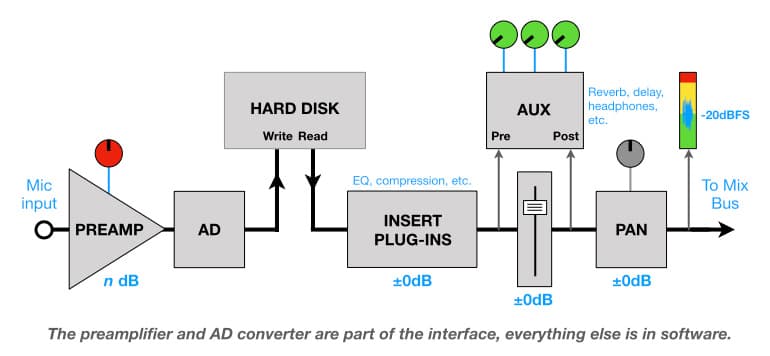
The illustration above shows the typical signal path when using an interface to record and mix music. Note how similar it is to the analogue signal path shown earlier? In practice, the DAW’s channel strip still begins with the mic preamp and ends with a fader feeding a pan/assign section. All the gain structure rules of the analogue signal path still apply because a) the digital signal path has a maximum level that we need to stay below to avoid clipping distortion, b) the digital signal path has a noise level that we need to stay above (low though it is), and c) an audio signal is still an audio signal regardless of whether its in volts or bytes. Collectively, these three facts mean the concepts of NOL, Headroom, S/N Ratio, Dynamic Range and so on still apply in the digital world. They just get easier to calculate and manipulate, as we’ll see in the next installment…
The DAW encourages us to record everything clean, directly out of the preamplifier, and apply all processing in the monitoring/mixing path (it is essentially in record and mix modes simultaneously). We can make multiple instances of our favourite plug-ins and apply them all over the mix with no need to record any sounds with effects or processing on them – a fact that many people fail to appreciate when complaining about the price of a plug-in. To put that into context, apart from the EQ found on every channel strip of the mixing console, the traditional 24-track analogue recording studio’s processing would typically consist of two or three reverb units, a couple of delays, four to six channels of compression and four to six channels of gates. That was it. You didn’t press your finger against the front panel of your Lexicon 480L and drag it left or right to get another one, and you didn’t press ‘+’ to get a new track. To make the most of the limited number of processors and tracks available it was prudent to record some sounds with processing applied, and old-school engineers learnt how to do that without regretting their choices later – just as guitarists had been doing for decades.
[On that topic, try telling any experienced electric guitarist that you intend to record the guitar clean and add the effects pedals later. It’s not going to happen because a) the effect pedals are part of ‘the sound’ and playing to ‘the sound’ is part of the performance, and b) experienced guitarists have already been through this disappointing process with some other engineer and know that it rarely sounds the same – it doesn’t matter if it ultimately sounds better or worse from the engineer’s point of view; what matters to the guitarist is that it’s not the same.]
With the exception of DSP algorithms that use astrophysics and information theory to do things that are practically impossible to do in the analogue domain (such as de-noising and de-clipping), our digital audio systems are fundamentally based on the analogue building blocks that preceded them, and when we start treating our digital signal levels the same way that we treat our analogue signal levels we find that our recordings, mixes and overall workflow improve because we’re treating our audio signals as, er, ‘audio signals’. So…
1) Set your gain to an NOL or Alignment Level rather than a Peak level, and always keep an eye on the gain structure as explained above (especially if you’re using any of the gain bending tricks shown in the next installment).
2) Inserting plug-ins on your signal’s channel strip in the DAW is the same as connecting processing to the insert point of the analogue channel strip. So use plug-ins in the signal’s channel strip for things that create replacement versions of the signal (e.g. compression, EQ, etc.) and that have output level controls to compensate for any changes in the gain structure.
3) Use the auxiliary sends for processing that creates new signals that need to be mixed alongside the original signal (e.g. reverb, delays, modulation effects, parallel compression, etc.), and bring those processors up on separate channels where they can be individually EQ’d (before and/or after the effect) and otherwise processed to knit them into the mix. (Make sure the effect’s blend control is set to 100% ‘wet’ or ‘effect’ to prevent it from adding more of the unprocessed sound to the mix.) This approach invariably sounds better than inserting the effect directly into the signal’s channel strip and using the plug-in’s blend control to determine the balance of dry/effected sound, and also avoids messing with the signal channel’s gain structure that you’ve worked so hard to preserve (leave that tomfoolery to the guitarists and their pedals). Having the effect plug-in on its own channel strip also allows it to be sent via the auxiliaries to another processor, such as sending the output of a delay to a reverb.
When you implement the three recommendations above you’ll find that your mixes are starting to sound more like [wait for it…] ‘mixes’, and that conveniently brings us back to the VU meter.
REAR VU MIRROR
In previous installments of this series a number of references were made to a relationship between perceived loudness and setting gain for individual channels or tracks. How is a signal’s perceived loudness related to setting the microphone gain? It’s not anymore, but it used to be – whether we realised it or not – and something beneficial happens when we bring perceived loudness back into the gain setting process. To understand that we need to reflect upon the VU meter, yet again…
As mentioned in a previous installment (Levels & History), the VU meter was designed to give an indication of the relative perceived loudness of different audio sources or signals. It’s reasonably reliable for vocals/dialogue and for mixing popular music, but its slow attack time means it is not reliable on individual close-miked sounds that have percussive envelopes. With experience we learn to compensate for the VU meter’s inadequacies, estimating where a signal’s level should appear on the meter scale based on its envelope. For example, when a close-miked kick drum reaches a level of around -10dB on the VU meter its Peak level is probably getting close to +6dB (as shown below). Some analogue multitrack tape recorders have peak-indicating LEDs built into their VU meters (Studer’s A827 had indicators for +6dB, +9dB and +12dB), which, combined with the VU’s metered level, give a good indication of a signal’s Crest Factor and prove very helpful when recording unfamiliar or unpredictable signals – especially if you know the level at which tape saturation begins.
You didn’t press your finger against the front panel of your Lexicon 480L and drag it left or right to get another one…

One of the most interesting and forgotten benefits of VU metering comes from the fact that in the days of analogue audio the VU meter was the primary level indicator when setting gain. The goal was to get the signal’s level as close to 0dBVU as possible without peaking (or going into excessive saturation if using analogue tape). Whether we realised it or not, the VU meter encouraged us to adjust the gains to bring all of our individual tracks to a consistent perceived loudness level, which is what 0dBVU ultimately represented. It wasn’t as accurate as today’s perceived loudness metering systems (such as LUFS), but by aiming for 0dBVU we were ultimately aiming for a perceived loudness.
In the peak-metered world of digital audio we’re encouraged to adjust gains towards a Peak level – and a bunch of tracks recorded to the same Peak level is a bad way to start a mix because the perceived loudnesses of the individual signals are all over the place and therefore so are the faders when mixing. In contrast, in the VU-metered world of analogue audio all signal levels are adjusted towards the same perceived loudness level – which is a better way to start a mix. Why?
At the heart of mixing for most forms of popular music is the notion that each of the core sounds in the mix (drums, bass, guitars, keyboards, vocals, whatever) should be clearly audible alongside every other core sound, which means they’ll usually have similar perceived loudnesses in the mix – give or take a few dB. If all of the core sounds have been captured at or around the same perceived loudness (whenever their Peak levels allow it), it means the mix can begin with all the faders at roughly the same level (typically at their 0dB or ‘Unity’ position) and most, if not all, of the individual sounds will be on a relatively level playing field. Within a few minutes we’ll have fader levels in place that we can build a mix from without pushing some faders all the way down to the bottom because their sounds have been captured at much higher perceived levels than everything else, and without pushing some faders all the way to the top to make their sounds audible alongside everything else. We’re also not using gain plug-ins or clip gain simply to bring signal levels up or down to levels that behave themselves in compressors and similar level-based dynamics processors. Furthermore, as with the Unity Gain approach discussed in the next installment, most of the mixing action is happening at the point where the faders have the highest resolution – around their 0dB or ‘Unity’ position, where big fader movements create small changes in perceived loudness and it’s easy to make precise adjustments and tweaks.
From that starting point we can use compression to control and match dynamics between individual sounds, we can use EQ and reverberation to add clarity, separation and depth to our sounds, and we can use automation for things that need real-time level changes. We can spend our mixing time focusing on creative decisions regarding how loud and clear we want one sound to be compared to another, rather than starting off with the analytical ‘screwdriver work’ required to get them all in the same perceived loudness ballpark. With the right processing and fader levels we can make some sounds quiet and distant while remaining clear and intelligible, and we can make other sounds boisterously loud and in-your-face without drowning out everything else.
Within a few minutes we’ll have fader levels in place that we can build a mix from…
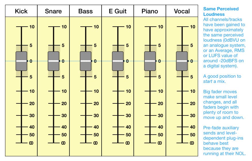
Experienced mixing engineers who honed their craft on analogue systems with VU meters will know the frustration of receiving a DAW session in which all tracks have been recorded to the same Peak level, resulting in perceived levels that are all over the place. Unless they’re skilled with batch processing apps, a big chunk of their session time will be wasted messing around with gain plug-ins, clip gain and automation to make the recorded levels suitable for mixing and processing without having faders up and down all over the place; in other words, making the signal levels right to the ear rather than the technology, which is where they should’ve been in the first place – just as the engineers and equipment designers of old knew. It’s little wonder that today’s superstar mixing engineers have assistants tasked with doing all the screwdriver work required to prepare the individual tracks of an incoming session for mixing…
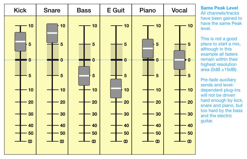
The technology is just a tool, and the digital audio tool is good enough that the only real concession we need to make for it is to avoid clipping, which is also one of the concessions we need to make for analogue audio. Other than that, the old school engineers and equipment designers who came up with the VU meter and the notion of a NOL were definitely on the right track (so to speak). They knew there was more to a signal than its Peak level, and they knew that aiming for a relative perceived loudness based on a Nominal Operating Level poised somewhere between noise and distortion is more important than getting the highest level possible.
POINTS OF VU
The mixing benefits described above are not specifically due to the use of VU meters, but due to setting microphone gains so that all signals have approximately the same NOL-based perceived loudness.
The VU meter is a hard task master that requires considerable familiarity and interpretation. You can get the same benefits with less hassle from other metering systems that attempt to show something similar to perceived levels, such as the Average and RMS options that are readily available on most DAWs (the VU meter is essentially an Averaging meter). Adjust your microphone gain so that the Average or RMS level is sitting around -20dBFS while ensuring the Peak levels conform to the recommendations given in the earlier instalment about Levels & Gain, and you’ll find everything in the mix falls into place faster and easier. You’ll also find that compressors and other level-sensitive processors behave themselves better too – especially those that emulate or model vintage analogue processors and therefore expect to see signals based around an NOL of -20dBFS (the recommended digital equivalent to +4dBu).
Conceptually, at least, using LUFS metering would be ideal because it provides a far more accurate indication of perceived levels than VU, Average or RMS metering. The most appropriate LUFS measurement for this application is the Integrated LUFS level, but that’s a long-term measurement taken over the duration of the signal and is therefore not practical for real-time metering and setting of microphone gain. However, if you’re curious or find yourself tasked with mixing a session of unruly tracks that were all recorded to a consistent Peak level, consider preparing the files in advance of mixing by setting their individual levels to the same Integrated LUFS level (try -20dB LUFS) whenever their Peak levels allow it.
Regardless of what metering system you use (Average, RMS, LUFS), if you can’t get a signal to sit around -20dBFS without clipping then you’re going to have a hard time making it work alongside sounds that do sit comfortably around -20dBFS. Reduce that signal’s level to avoid clipping, and be prepared to use compression and/or automation if it’s meant to play a significant role in the mix. Also note that some percussive sounds are going to be difficult to capture in this manner – for example, an ‘80s pop kick drum with a click pad, close-miked with a Beyer M88 at 8cm from where the beater hits the skin, is never going to look ‘right’ on any metering system.
The average DAW provides a huge arsenal of metering, making it possible to monitor numerous aspects of a microphone’s signal and work out the right amount of gain to capture it properly. Assuming you’ve chosen a microphone with appropriate specifications for Sensitivity, Equivalent Noise Level and Maximum SPL to suit the sound source (as discussed in previous installments), capturing to a standardised perceived level or similar (VU, Average, RMS or LUFS) rather than a standardised Peak level means that the right amount of gain is used on each signal. That usually equates to less noise, more headroom and better overall sound quality in the mix.
NEXT LEVEL
Further to the level recommendations referenced above and given in an earlier installment (see ‘Levels & Gain’), if you are using separate preamplifiers and AD converters you can add the following refinement to the signal path to take care of extremely dynamic signals. It’s also possible to use this approach if you’re using a field recorder that contains a compressor/limiter with comprehensive user-adjustable features.
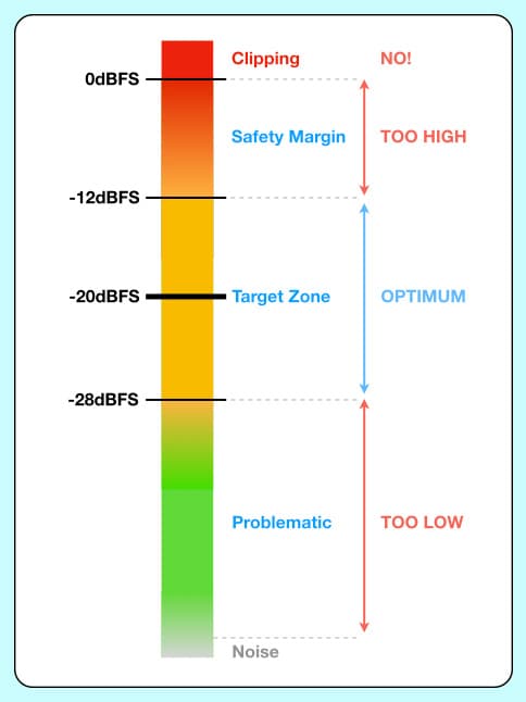
A soft-knee peak-sensing compressor with a threshold equivalent to -12dBFS (i.e. the threshold is set so that gain reduction only begins when the metered Peak level exceeds -12dBFS), with a 2:1 ratio and very fast attack and release times should only affect peaks that venture above -12dBFS (into the Safety Margin), and minimises the chance of clipping without resorting to hard limiting – which often sounds only marginally better than clipping.

The illustration above shows a top-to-bottom signal path using a professional analogue preamplifier, analogue compressor and AD converter, all aligned so that 0dBVU = +4dBu = -20dBFS, and set up as described above. The soft knee ensures the compression comes in gently, being barely noticeable on peaks that don’t go too high over the threshold.

The goal, of course, is to set the preamplifier’s gain low enough to keep the signal’s Peak levels below -12dBFS so that the compressor is never needed – but if any peaks do go above -12dBFS the compressor will ensure the signal remains useable, as shown below where the Peak level of the input signal exceeds -12dBFS.

In this scenario, any signal peaks that remain high enough to exceed 0dBFS after compression will have most likely clipped much earlier in the microphone preamplifier or compressor before entering the digital system – unless those devices have unusually high headroom. For example, with a threshold equivalent to -12dBFS and a ratio of 2:1, the input signal needs to exceed the threshold by 24dB or more in order to reach 0dBFS. If -20dBFS is equivalent to the preamplifier’s NOL of +4dBu, a threshold equivalent to -12dBFS is 8dB above -20dBFS and therefore 8dB above +4dBu, which is +12dBu. 24dB above that is +36dBu, a level that’s highly unlikely from any affordable preamplifier on the market.






Thanks Greg, you have saved me from reiterating the same information. Love the sliding graphics!
Sorry for the very delayed response, Cliff, and glad you like the article – especially the sliding graphics, LOL!
Excellent material for my teaching of sound engineering at TAFE. Well done Greg.
Sorry for the delayed response, Gary. Most of this series has been written with audio engineering students in mind, as a kind of reference or resource. The forthcoming instalments/installments (we can never agree on that spelling LOL!) will continue and also get more practical as we start putting it all into practice.