
Microphones: Gain Bending
In the thirteenth installment of this on-going series Greg Simmons tells us when, why and how to break the gain structure rules he laid out earlier…
In the previous installment we looked at gain structure, using a typical analogue console’s input channel as an example. We saw how to configure the channel strip so that we can accurately set the preamplifier’s gain to bring the microphone signal up to the NOL, and we saw how the other components in the signal path can shift the signal level away from the NOL. We also saw how to compensate for those level shifts, returning the signal’s level to the NOL without risking clipping or excessive noise. We ultimately arrived at a set of rules for setting the gain and maintaining the signal level at the NOL.

In this installment we’re going to look at situations that justify bending, perhaps even breaking, the gain rules in the interests of capturing a useable audio signal in difficult circumstances…
GAIN BENDING
As the saying goes, ‘rules are made to be broken’ – but it would be foolish to break a rule without knowing why it exists and, therefore, why it is worth breaking. The NOL provides a good example; for most forms of popular music the industry standard NOL of 0dBVU =+4dBu = -20dBFS works well – it’s high enough to overcome the noise of the analogue parts of the signal path, but low enough to provide sufficient eadroom. As shown in the previous installment, setting the gain to bring the microphone signal up to the NOL is a good rule to follow when capturing lots of different sounds that are intended to be mixed together. There are times, however, when we can benefit from bending the NOL rules.
OPTIMISING FOR HEADROOM
In situations where high headroom is the priority, it’s beneficial to keep the signal levels below the NOL. A good example is recording or mixing a live performance of music that has high dynamic range (orchestral, jazz, percussion ensemble, etc.) – a situation where setting gains to reach the NOL may not leave enough headroom for peaks. In these scenarios we can accept a bit more noise in return for higher headroom and less chance of clipping. As we’ll see, the increase in noise level is usually less than the increase in headroom, making it a worthwhile compromise in situations where sudden high transients are anticipated and you’ve only get one chance to get it right. To quote Rupert Neve yet again, “a good engineer will not let his signal clip more than once a year”.
Unity Gain
This brings us to the Unity Gain approach. It’s primarily used in live performance mixing applications where the background noise of the audience and venue tend to mask any additional noise (in the form of ‘hiss’) coming from the PA system, and where a regularly clipped signal – even if barely perceptible – is a fast-track to fatiguing mixes and burnt-out high frequency drivers. The Unity Gain approach uses only as much gain as is required for the mix in the venue, thereby retaining as much headroom as possible.
The Unity Gain approach starts with every channel’s gain set to minimum and its fader at ‘Unity’, i.e. the ‘0dB’ marking where it isn’t affecting the level of the signal coming out of the channel strip. Theoretically the mixing console’s Master fader is also set to Unity, but in many sound reinforcement situations the Master fader is also the engineer’s master volume control and is therefore set to whatever level usually provides an acceptable SPL into the venue (typically shown as a black line on a piece of white electrical tape placed alongside the fader). More about the Master fader shortly…
…it would be foolish to break a rule without knowing why it exists…
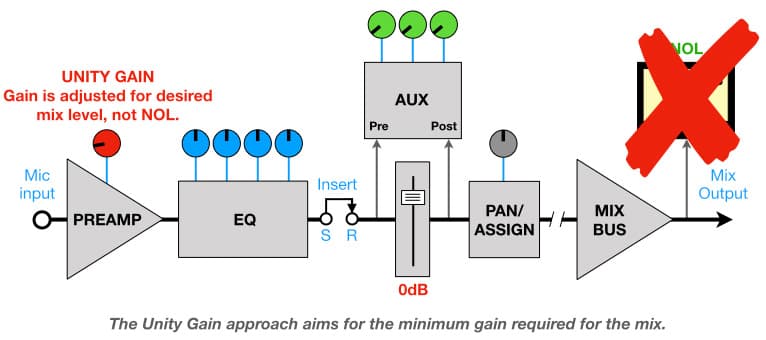
With all the channel faders at their Unity positions, the basic mix is made on the gain controls. Each channel’s gain control is turned up until its sound reaches the desired level in the mix as it is heard in the venue. Eventually the basic mix, or ‘balance’, exists on the gain controls when all the faders are at their Unity position – in essence, putting all of the faders at Unity becomes a ‘preset’ for the basic mix that can be tweaked from song to song. Conveniently, this is also where the faders have the most resolution (i.e. big fader movements make small level changes). The process of mixing the live performance involves moving individual faders up and down by a dB or two as required to highlight a solo, fix a particularly loud or soft keyboard patch, ride a performer’s dynamics, or compensate for a performer moving around the microphone. Returning a fader to its Unity position returns its signal to the normal position within the balance.

The Unity Gain approach is not only convenient, it’s also good for creating live mixes with lots of headroom – a characteristic that is often described as sounding ‘open’, ‘airy’ and/or ‘effortless’ (assuming the rest of the PA’s amplifiers and speakers have sufficient headroom). There are, however, some things to be aware of…
Unity Gain: Terminology
We must be careful with our use of the term ‘headroom’ here. As a formal specification the term ‘headroom’ refers to the difference between a circuit’s specified NOL and its clipping point, and is expressed in dB. When discussing the Unity Gain approach we have to remember that we are intentionally using less preamplifier gain than is required to reach the circuit’s NOL. By aiming for a lower average signal level we are artificially lowering the NOL on a per channel basis, and thereby increasing the difference between the signal level and the clipping point. In other words, we are increasing the headroom from the signal’s point of view, but the circuit’s formally specified ‘headroom’ stays the same because it is measured against the circuit’s formally specified NOL. So we always have to keep in mind which ‘headroom’ we’re talking about: the circuit’s or the signal’s…
It’s also important to remember that artificially lowering the ‘NOL’ brings the signal level closer to the noise floor – the signal gets more headroom, but it also gets more noise. So the Unity gain approach is like getting on your hands and knees to crawl through a low passageway; there’s less chance of bumping your head (clipping) but you’re going to get more dirt (noise) on your hands.
Unity Gain: Monitors & Master Faders
If the monitors/foldback mixes are being created on a mixing console configured for the Unity Gain approach it’s important to ensure that each channel has enough gain to provide a useful signal level to the monitors/foldback system. The amount of gain used on each channel ultimately depends on the setting of the console’s Master fader because that affects the level of the mix coming out of the console, which in turn determines the SPL of the mix in the venue and, therefore, how much gain each individual sound requires to reach its desired SPL within the mix.
If the Master fader is set too high it means that less gain is required for each channel’s signal to reach the desired SPL in the venue. This gives each channel’s signal more headroom (satisfying the goals of the Unity Gain approach), but it also means a channel’s signal level may be too low to provide a useful level to the monitors/foldback system – and perhaps also to any processors connected to the auxiliary sends or insert points.
Conversely, if the Master fader is set too low it means each channel is using more gain than necessary, defeating the purpose of the Unity Gain approach.
In any ‘monitors/foldback from the same console’ scenario (whether using Unity Gain or not), it is wise not to change the gain settings after the basic balance has been established unless there’s been a significant change on stage. Changing a signal’s gain also changes its level going to the monitors/foldback system, which usually has an adverse affect on the performers.
If the monitors/foldback signals are being provided by a separate mixing console (typically on the side of the stage), the above considerations about the Master fader and monitors/foldback levels are irrelevant.
Unity Gain: Recording
If the live performance is being recorded from within the console (e.g. USB stick or hard drive) or via its Direct Outputs, the recorded levels of individual tracks will be relatively low in accordance with the lower gains used in the Unity Gain approach. This is rarely a problem in practice because these types of recordings from the console are usually for archival purposes with an optimistic element of ‘maybe get lucky and capture something worth sharing’, in which case a little more console noise is easy to accept. Any serious recording of a live performance takes splits from the microphones on stage, along with additional microphones to capture the audience reaction and perhaps other microphones on stage that are better suited to sound recording rather than those used for sound reinforcement.
Unity Gain: Practical Example
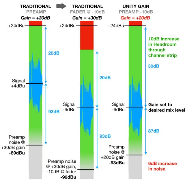
The illustrations below show how the Unity Gain approach offers more headroom at the expense of more noise. For this example we’ll assume an input signal from the microphone that requires +30dB of gain to reach the NOL of +4dBu, but requires only +20dB of gain to reach the desired level within the mix (which turns out to be -6dBu, or -10dBV).
Let’s start with the traditional approach and set the gain at +30dB to reach the console’s NOL. According to the EIN curve we’ve been using throughout this series (reproduced below) at +30dB of gain the noise level at the preamplifier’s output is -89dBu.
…you’re going to get more dirt on your hands.
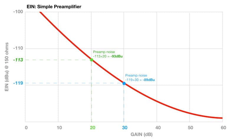
With a signal level of +4dBu and a preamplifier noise level of -89dBu, there’s 20dB of headroom through the channel strip and the preamplifier noise at the output is 93dB below the signal level.
We’ve already established that the signal only requires +20dB of gain to reach the desired level in the mix of -6dBu, so with +30dB of gain the signal is 10dB higher than we need it to be in the mix. That means with +30dB of gain we’ll be pulling the fader down by 10dB, taking the signal level and the embedded preamplifier noise level down by 10dB and resulting in a post-fader signal level of -6dBu, a post-fader preamplifier noise level of -99dBu, 20dB of headroom through the channel strip before the fader, and 30dB of headroom after the fader.
What if we want more than 20dB of headroom through the channel strip before the fader (i.e. through the EQ and any inserted processing), in case of unexpected peaks? This is where the Unity Gain approach becomes useful…
We know that the signal only requires +20dB of gain from the preamplifier to reach the desired level within the mix of -6dBu. According to the EIN curve, at +20dB of gain the noise level at the preamplifier’s output will be -93dBu. With a signal level of -6dBu and a noise level of -93dBu, the noise at the preamplifier’s output is now 87dB below the signal level. With the fader at the Unity Gain (0dB) position, the post-fader signal level will be -6dBu and the post-fader preamplifier noise level will be -93dBu. The post-fader signal level of -6dBu and post-fader headroom of 30dB remain the same. The preamplifier noise has increased by 6dB (from -99dBu to -93dBu) and is now 87dB below the signal level, but we have the benefit of 10dB more headroom throughout the channel strip for unexpected peaks.
Another VU of Unity Gain
Here’s another look at the Unity Gain approach, this time using a simplified version of the gain structure diagrams explained in the previous installment. To align these diagrams with the example given above we’ll assume the microphone is providing a signal level of -26dBu and has an output impedance of 150 ohms, the level coming out of the preamplifier at the NOL is +4dBu, and the desired level for this particular sound source in the mix is -6dBu ( which is equivalent to -10dBVU).
The illustration below shows the traditional approach of setting gain, as detailed in the previous example. The preamplifier’s gain has been set to +30dB, bringing the microphone’s signal level of -26dBu up to the preamplifier’s NOL of +4dBu. According to the EIN curve we’ve been using throughout this series, with +30dB of gain and a microphone impedance of 150 ohms the preamplifier’s noise is -89dBu. That puts the preamplifier’s noise level 93dB below the preamplified signal’s level of +4dBu (i.e. +4dBu – -89dBu = 93dB)
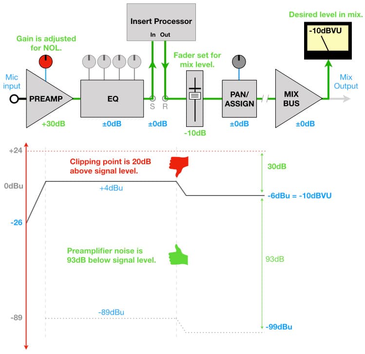
There is 20dB of headroom between the output of the preamplifier and the input of the fader. The fader has been pulled down to -10dB to bring the signal level of +4dBu down to the desired level of -6dBu in the mix.
The result is an output signal level of -6dBu (-10dBVU) with 20dB of headroom between the output of the preamplifier and the input of the fader, 30dB of headroom at the output of the channel, and the preamplifier noise level of -99dBu that sits 93dB below the signal level.
The illustration below shows the Unity Gain approach. The fader has been set to its Unity (0dB) position, and the preamplifier’s gain has been adjusted to bring the microphone signal’s level of -26dBu up to the desired mix level of -6dBu – which requires only +20dB of gain compared to the +30dB required for the traditional approach – as we established in the previous example.

According to the EIN curve we’ve been using throughout this series, with +20dB of gain and a microphone impedance of 150 ohms the preamplifier’s noise is -93dBu, which puts it 87dB below the signal level (.e. -6dBu – -93dBu = 87dB).
The fader is set to its Unity position of 0dB, which means the signal level remains consistent as it passes through the fader.
The result is an output signal level of -6dBu (-10dBVU) with 30dB of headroom at the output of the channel, as in the previous example, but the signal now has 30dB of headroom as it passes through the EQ and insert point instead of the 20dB of headroom offered in the traditional approach. The trade-off for that extra 10dB of headroom is 6dB more preamplifier noise when considered in absolute terms (-93dBu vs -99dBu), and also if measured relative to the signal level (87dB vs 93dB).
With the Unity Gain approach demonstrated here we get 10dB more headroom through the channel strip, but at the expense of 6dB more noise. Given a choice between noise and clipping, any sensible engineer will take the noise.
OPTIMISING FOR LOW NOISE
In situations where we need very low noise but don’t need much headroom it makes sense to aim for a higher signal level than the NOL. In other words, using more gain. We’ve already established that using more gain means more noise from the preamplifier, so how does using more gain give us less noise? Let’s see how they do it in another industry that has to deal with similar challenges…
ETTR: Expose To The Right
One of the fundamental goals of photography is to capture a properly exposed image, which is achieved by choosing an appropriate combination of camera parameters (lens, aperture, shutter speed, ISO) to get the right amount of light onto the camera’s sensor or film. The goals are a) getting enough light into the camera to overcome visual noise and avoid ‘crushing the shadows’ (i.e. losing detail in dark areas), while b) preventing too much light from getting in to the camera to avoid ‘blowing out the highlights’ (i.e. going beyond 100% white and into visual clipping). The techniques used to achieve this differ between film photography and digital photography, just as they do between recording to analogue tape or a digital storage medium. For this analogy we’ll stick to digital photography…
Fine art photography and landscape photography are two situations that present the challenge of getting enough light into the camera to minimise noise and preserve detail in the shadows without blowing out the highlights. To overcome this challenge photographers sometimes use a two-step technique in which they intentionally over-expose the shot to capture an image containing more light than required without clipping the highlights, and then under-expose the image in post-production to return the image to more natural light levels. This technique is called ‘Expose To The Right’ (ETTR) because it refers to capturing more light than necessary in the right side of the histogram – a visual display that shows the levels of the image’s colour spectrum, with solid black at the far left and solid white at the far right. When done well and under appropriate circumstances, the result of this two-step ‘over-expose/under-expose’ process is an image containing more detail and less noise than the camera/lens combination could provide on its own if aiming for a ‘proper’ exposure with the available light.
…how does using more gain give us less noise?

It’s worth noting that the benefits of the ETTR approach are often subtle and only worthwhile in situations where the image will be blown up to a very large size for close viewing or zoomed in at microscopic levels to study tiny details.
GTTM: Gain To The Max
A similar two-step approach can be used for contemporary audio engineering. For the purposes of this audio analogy, let’s consider the ‘desired exposure’ as being equivalent to the NOL, ‘visual noise’ as being equivalent to audio noise, ‘blowing out the highlights’ as being equivalent to clipping the peaks of an audio signal, and ‘crushing the shadows’ as being equivalent to burying the signal in noise. The ETTR technique is, therefore, the photographic equivalent of recording at the highest level possible without clipping and then reducing the signal level back to the NOL before mixing or other post-production so that a) it doesn’t clip with the slightest EQ boost, b) it behaves properly with dynamic processors (especially emulations of vintage compressors/limiters that assume the signal has a NOL of +4dBu or an Alignment Level of -20dBFS), and c) its fader isn’t pushed so far down that small movements make big changes.
Let’s call this approach GTTM, for ‘Gain To The Max’. It’s a term that’s loaded with rabble-rousing ‘crank it up’ attitude, but remember that your recording equipment doesn’t give a dB for your attitude – if you push it too hard it will clip and you’ll be leaving your attitude at the DAW while humbly doing the walk of shame to RX’s De-Clip algorithm, fingers crossed in the hope you’ll return with something useable.

GTTM: How Does It Work?
We’ve established in previous installments of this series that more gain means more noise out of the preamplifier, so how does the GTTM approach give us less noise? Let’s return to the EIN curve of the simple preamplifier we’ve been using throughout this series.

At +10dB of gain the preamplifier’s output noise is -95dBu, while at +50dB of gain it is -77dBu. As expected from the EIN curve, we see that the noise level coming out of the preamplifier is higher at +50dB of gain than it is at +10dB of gain – in fact, it’s 18dB higher (95 – 77 = 18). Nothing new there, but…
How does that increase in the noise level compare to the associated increase in the signal level?
Increasing the gain from +10dB to +50dB results in a 40dB increase in the signal’s level with only an 18dB increase in the preamplifier’s noise level. In other words, the signal level has increased more than the noise level – in this example the noise level at +50dB of gain is actually lower than it is at +10dB of gain if we measure it relative to the signal level. How does that work?
The graph below is based on the EIN curve above and shows how the signal level and preamplifier noise level (measured at the output of that particular preamplifier) change with increasing gain:
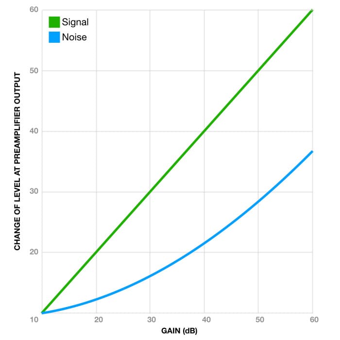
Using a gain of +10dB as a starting point, we see that the signal level (green) increases in direct proportion to the gain but the noise level (blue) increases by a smaller proportion. A larger gap between the green and blue lines means a lower noise level relative to the signal level. This is the core of the GTTM approach.
GTTM: Backtracking
In the ninth installment of this series, ‘Levels & History’, we saw that the preamplifier’s S/N Ratio was calculated as follows:
Preamplifier S/N Ratio = Nominal Operating Level – Noise Level
The formula assumes the signal is being amplified to reach a known reference level at the output (the NOL), and the S/N Ratio is calculated as the difference between that known reference level and the preamplifier’s noise level at the output.
In the seventh installment of this series, ‘Noise 2’, we saw how to calculate the noise at the output of the preamplifier based on the EIN curve and the amount of gain in use. The formula is:
Noise Level = EIN + Gain
The following formula, derived through substitution, let’s us determine the S/N Ratio at the output of the preamplifier for any given amount of gain:
Preamplifier S/N Ratio = NOL – (EIN + Gain)
The graph below shows how the preamplifier’s S/N Ratio decreases (i.e. gets worse) with increasing gain for the preamplifier we’ve been using throughout this series. If we know how much gain will be required to bring the microphone signal up to a known level (in this case the NOL of +4dBu), we can project upwards from the graph’s horizontal axis to the curve and then project to the left to see the S/N Ratio on the vertical axis. For example, at +30dB we see that the preamplifier’s S/N Ratio is 93dB.
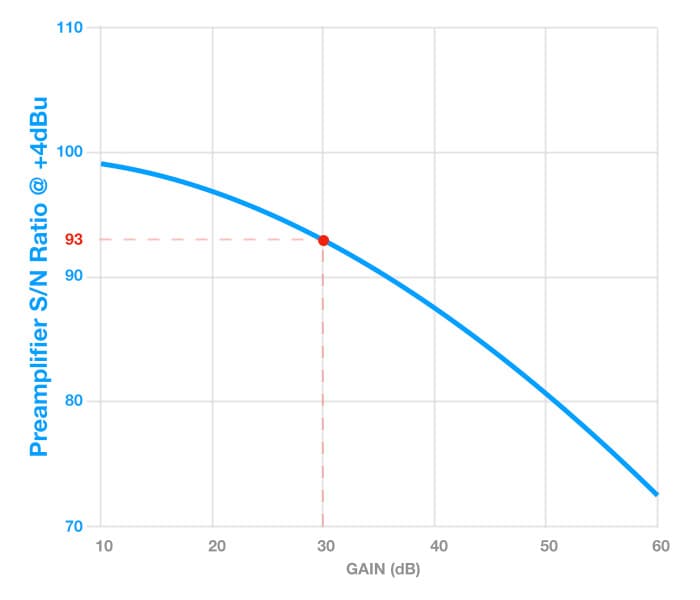
The GTTM approach ignores the NOL, meaning the amount of gain required is no longer based on taking the signal level up to the NOL. Instead, it’s based on taking the signal’s level up to the highest level possible without clipping.
GTTM: Terminology
The GTTM approach essentially replaces the NOL with the maximum level possible for the signal itself, which brings us to a dubious ‘specification’ we’ll call the signal’s S/N Ratio. It’s dubious because the noise is no longer being compared to a consistent reference value (e.g. the NOL) but is instead being compared to an audio signal with a continuously changing level – which means the signal’s S/N Ratio will be changing with fluctuations of the audio signal level and would therefore need to be averaged over its duration to make any sense in terms of comparing one device to another. It’s not a form of measurement that could be repeated by different manufacturers and presented as a formal specification unless all manufacturers had access to the same audio signal – which is highly unlikely. Anyone attempting to make it a proper specification would be laughed out of the room.
Nonetheless, the concept of the signal’s S/N Ratio is helpful to understand how the GTTM concept works because, ultimately, the signals we’re capturing are not conveniently consistent test tones. If we’re going to bend the rules we might as well bend the specifications while we’re at it…
GTTM: Signal’s S/N Ratio
We can calculate the signal’s S/N Ratio with the following formula:
Signal’s S/N Ratio = Signal Level – Noise Level
The graph below shows the signal’s S/N Ratio as the gain is increased from +10dB to +60dB, using the same preamplifier we’ve been using throughout this series.
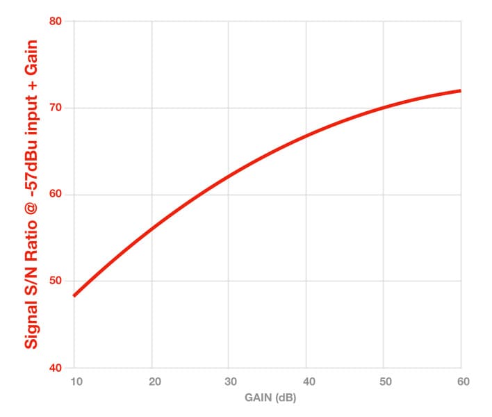
The signal’s S/N Ratio calculations are based on a signal level of -57dBu going into the preamplifier from the microphone, which is equivalent to the output of a Shure SM7B (150 ohms output impedance) with 94dB SPL at the diaphragm.
At +10dB of gain the preamplifier has a noise level of -95dBu at the output (as established earlier), while the signal level at the preamplifier’s output is -47dBu (i.e. -57dBu + 10dB). Here’s the maths to determine the signal’s S/N Ratio:
Signals’s S/N Ratio = -47dBu – -95dBu = 48dB
What happens to the signal’s S/N Ratio when using +50dB of gain? At +50dB of gain the preamplifier has a noise level of -77dBu at the output (as established earlier), while the signal level at the preamplifier’s output is now -7dBu (i.e. -57dBu + 50dB). What happens to the signal’s S/N Ratio?
Signal’s S/N ratio = -7dBu – -77dBu = 70dB
So, increasing the gain from +10dB to +50dB gave us a 40dB increase of the signal level (from -47dBu to -7dBu) with an accompanying increase of 18dB in the preamplifier noise level (from -95dBu to -77dBu), which resulted in a 22dB improvement (i.e. from 48dB to 70dB) in the signal’s S/N Ratio. That’s a worthwhile improvement, but only if the signal doesn’t clip in the process – otherwise, you’ll be doing that cross-fingered walk of shame to RX’s De-Clip algorithm…
GTTM: Putting It All Together
The graph below overlays the preamplifier’s S/N Ratio (blue) and the signal’s S/N Ratio (red) as the gain is increased from +10dB to +60dB. The actual values of the S/N Ratios (shown on the left and right axes) are less important; what matters to the GTTM approach is that the signal’s S/N Ratio improves with increasing gain (i.e. the preamplifier’s noise level becomes less significant when compared to the signal’s level).

For those wondering how these two curves can co-exist, it’s important to consider the differences between them. The blue curve assumes a decreasing input signal level that requires increasing amounts of gain to maintain a consistent output signal level. Because the output signal level remains the same, the numbers confirm what the EIN tells us: the noise increases with gain, and therefore the preamplifier’s S/N Ratio decreases (i.e. gets worse) with gain.
In contrast, the red curve assumes a consistent input signal level being amplified at increasing amounts of gain to ultimately reach the maximum possible output signal level; the signal level at the output increases with gain at a larger rate than the noise level increases, meaning the signal’s S/N Ratio increases (i.e. gets better) with gain.
GTTM: Practical Example
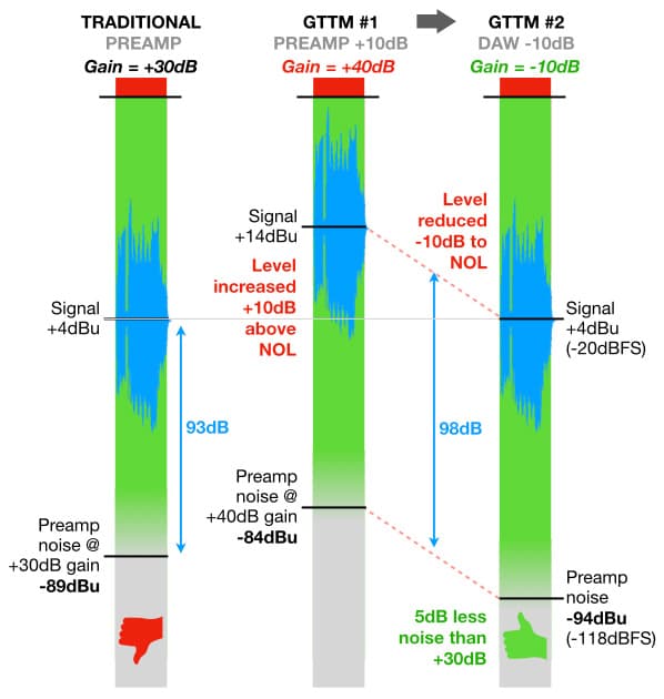
The GTTM approach performs well with budget preamplifiers and interfaces. Let’s put it into practice. For this example we’re going to abandon the notion of the signal’s S/N Ratio because it’s too dubious to take seriously – you can’t measure or compare something against a constantly changing reference like an actual audio signal, that’s like trying to measure someone’s height while they’re jumping up and down. Instead, let’s assume a consistent input signal level that requires +30dB of gain to reach the NOL of +4dBu (as used for the earlier example of the Unity Gain approach). According to our EIN curve, at +30dB of gain the noise level at the preamplifier’s output will be -89dBu. With an output signal level of +4dBu the preamplifier noise of -89dBu is 93dB (+4 – -89) below the signal level, as shown on the first meter in the illustration below.
Let’s say the signal has a relatively small Crest Factor and therefore does not require much headroom, allowing us to push the preamplifier’s gain up to +40dB without clipping. What happens to the signal level and the noise level?
At +40dB of gain the signal level at the preamplifier’s output increases to +14dBu. According to our EIN curve, at +40dB of gain the noise level at the preamplifier’s output will be -84dBu. With an output signal level of +14dBu the preamplifier noise of -84dBu is 98dB (+14 – -84) below the signal level, as shown on the second meter.
When we complete the second step of the GTTM process and reduce the level of the captured signal in our DAW by 10dB to bring it back down to the NOL of +4dBu, the preamplifier noise (which is embedded into the signal) will be reduced with it and remain 98dB below the signal level. The result is a signal level of +4dBu with a noise level 98dB below it, as shown on the third meter. That’s 5dB less preamplifier noise compared to using +30dB of gain. To get that 5dB reduction in noise we had to accept a higher risk of clipping while recording due to using 10dB more gain than required and therefore having 10dB less headroom.
To take advantage of that noise improvement in a multitrack music mixing scenario without experiencing the numerous level problems described in the ninth installment of this series (see ‘0dBFS ≠ 0dBVU’), we should take the extra step of reducing the signal levels back to the NOL to regain their headroom before further processing and mixing. In the GTTM example given above we added 10dB more gain before recording, therefore we’d have to reduce the recorded signal’s level by 10dB before attempting any further processing. This could be done with clip gain or a gain plug-in at the top of the channel strip, or it could be done by a batch processing app before the file has been loaded into the DAW.
…the GTTM approach performs well with budget preamplifiers and interfaces.
When To GTTM?
The GTTM approach is a gateway to the level chaos of the early days of digital systems (as described in the ninth installment of this series) unless you’re prepared to do the extra step of reducing the signal level(s) back to the NOL or Alignment Level before mixing or post-production. That’s okay for a direct-to-stereo music recording, one or two tracks of dialogue (podcast, Youtube, talking book, etc.) or a couple of troublesome sounds in a multitrack recording, but doing it across all tracks in a multitrack studio scenario with the aim of making a very quiet multitrack recording can be a time-consuming process requiring extensive use of clip gain and/or utility plug-ins to bring all the individual tracks back down to the NOL or Alignment Level before mixing. [If you have the luxury of time you can make a note of how much additional gain is applied to each individual track (beyond the gain needed to reach the NOL), and then reduce the level of each track accordingly before starting the mix.]
Recording with a higher gain than necessary also increases the risk of feedback if you’re recording and monitoring in the same room and forget to mute the mic before engaging the speakers, or if a performer hangs the headphones over the microphone before leaving the room. It’s obviously a no-no for live sound reinforcement applications…
It can, however, be helpful for situations where noise is an issue – in particular, capturing low SPL sounds with low Sensitivity passive microphones connected to budget preamplifiers/interfaces. You’d be better off using a microphone with higher Sensitivity and/or a preamp with higher and quieter gain, but if your favourite Youtuber insists that a vintage ribbon microphone has the best tonality for recording pins dropping on cushions then by all means knock yourself out – and back in again – with GTTM.
SUMMARISING UNITY GAIN & GTTM
The Unity Gain and GTTM approaches have their supporters and detractors. Sadly, many don’t fully understand the concepts and will preach them blindly after one good experience or disparage them deafly after one bad experience. They are simply alternative approaches to using gain that benefit certain situations, and those who understand the concepts know when to use them and when not to. Some situations might benefit from a mixture of both, using the Unity Gain approach for sounds that require more headroom and the GTTM approach for sounds that require less noise.
It’s all part of ‘gain bending’, of course. Rules are apparently made to be broken, but it’s not until you fully understand the rules that you can break them with intent.
MAGNETIC SATURATION
In the previous installment we saw how to use an insert device’s Output Level control to return the channel signal’s level back to the NOL (see ‘Compensating For Insert Processing’). From a ‘gain bending’ point of view the insert device’s Output Level control could be used as an additional source of gain or attenuation if necessary. For example, when inserted into the channel strip it could provide additional gain if the preamplifier’s gain is insufficient. There’s more to it than that, however…
In a traditional multitrack studio with analogue tape recorders it’s possible to use a compressor (or similar processor with an Output Level control) for ‘gain bending’ purposes by inserting it between the console’s Bus Output and the tape recorder’s track input.
One example of this application is when the engineer wants to keep the level coming out of the console relatively low to avoid clipping the Bus Output circuit, but increases the Output Level of the compressor to hit tape harder for more tape saturation.
It’s all part of gain bending, of course.

Another example is when the engineer prefers the sound of overdriving the mixing console’s Bus Output circuits – particularly if the console uses transformer-balanced outputs. The goal is to push the channel strip’s output signal at the fader to a higher level than the NOL to drive the Bus Output’s transformer into saturation, and use the compressor’s Output Level to reduce the signal’s level before it enters the multitrack recorder (analogue or digital) to minimise tape saturation and/or clipping.

Both scenarios may require adjustment of the signal level returning into the mixing console from the tape recorder, but both cases represent creative uses of ‘gain bending’.
SPECTRAL BENDING WITH MICROPHONES
Here’s another technique we can borrow from the analogue world and re-purpose for the digital world…
To minimise noise, many analogue audio systems rely on a two-step process known as ‘pre-emphasis/de-emphasis’. The ‘pre-emphasis’ step of the process applies a high frequency boost in the signal path at a point before the signal is exposed to the noise. The ‘de-emphasis’ step of the process applies a mirror-image high frequency cut in the signal path after the signal has been exposed to the noise.
When set up correctly the de-emphasis process returns the signal to its original frequency spectrum, i.e. the frequency spectrum before the pre-emphasis was applied. The added noise did not get the pre-emphasis’ high frequency boost, however, which means its high frequency content (usually the most audible component of noise) is reduced by the de-emphasis. The end result is that the signal is returned to its original frequency response, but the noise is less audible.
It’s a trick that’s used in analogue tape recorders (NAB and IEC curves), vinyl cutting and playback (RIAA curves), FM radio broadcasts and other situations where the signal is exposed to considerable noise. It’s even an option in digital PCM systems such as DAT and CD – although it’s rarely needed or used in those systems nowadays.
Recording engineers working with analogue tape (especially the early lower coercivity tapes up to and including Ampex 456) would often apply their own subtle pre-emphasis/de-emphasis by EQing a sound to make it a dB or two brighter than desired before recording it to tape, and reducing it appropriately on playback. This would further reduce the audibility of tape hiss – especially on sounds that did not contain much high frequency energy to mask the hiss – while also compensating in advance for the subtle loss of high frequencies that occurs due to the many playbacks of an analogue tape throughout the duration of a large recording session.
We can use a similar trick when capturing very quiet sounds by choosing a microphone that delivers a brighter sound than desired, and then applying a carefully-tailored EQ (i.e. an inverted version of the microphone’s frequency response) to reduce the sound’s brightness. This will ‘flatten’ the microphone’s frequency response to deliver a more accurate reproduction of the original signal while simultaneously reducing the high frequency component of any noise that was added during or after the capture process (e.g. microphone self-noise, preamplifier noise, tape hiss, etc.). The microphone’s bright frequency response provides the pre-emphasis, and the EQ we apply provides the de-emphasis. There may be the subtle analogue-like ‘softening’ or ‘smearing’ of transients caused by the phase response of the chosen EQ, but that’s an aesthetic trade-off against the benefit of less noise so choose whichever sounds best. If the EQ plug-in has an ‘Amount’ control or similar that controls the overall amount of EQ being applied (as seen in iZotope’s ‘Ozone’), then we can tweak how much of the de-emphasis EQ is used to achieve the desired balance of the microphone’s inherent tonality and the amount of noise reduction.
Lewitt’s LCT540 Subzero large diaphragm cardioid condenser is an excellent choice for this approach. Its low Self Noise of 4dBA and high Sensitivity of 41mV/Pa make it a good choice for capturing very quiet sounds, but its frequency response allows us to take the fight against noise a step further. It exhibits a gradual rise that begins at 1kHz, climbs to just over +5dB at around 12kHz, then drops down to 0dB at 20kHz. It’s ideal for a pre-emphasis application. By creating an EQ curve that closely mimics the LCT540 Subzero’s frequency response and then inverting it (i.e. turning all the boosts into cuts, and all the cuts into boosts), we’ll have a corresponding de-emphasis curve that linearises the microphone’s frequency response while also reducing any noise introduced by the preamplifier and signal path.
…the signal is returned to its original frequency response, but the noise is less audible.
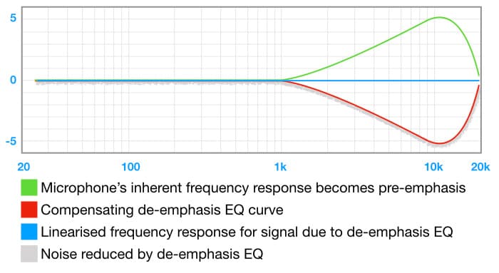
The illustration above shows a highly smoothed version of the LCT540 Subzero’s frequency response, which is sufficient for this example. With the compensating EQ applied we can see that the microphone’s frequency response is linearised while the noise is reduced: 1dB at 2kHz, 2dB at 3kHz and so on up to 5dB at 10kHz. Depending on the frequency spectrums of the sound source and the noise, those reductions in noise could be quite significant. The same trick can be used with any microphone that exhibits a significant increase in midrange and/or high frequencies – if the microphone delivers more upper midrange and/or high frequencies than are required for the mix, we can use it for pre-emphasis.
…AND BACK TO MICROPHONES
Over the last five installments of this series we’ve explored numerous concepts related to signal levels, gain and gain structure. We’ve seen recommended recording levels, discussed important concepts such as the NOL, and looked at specifications such as Noise Floor, Headroom and Dynamic Range. We’ve seen how all of these things relate to choosing microphones and setting gain, and we’ve even made some rules and broken them. Anyone jumping into this series from any of the last five installments would wonder why it’s titled ‘Microphones’ when there has not been much discussion about microphones themselves. Fear not! The next installment moves decisively back to microphones as we begin exploring frequency responses and polar responses.




Oh yea, I have bushed off the “walk of shame” many times worrying about foh and f/b thinking that they will fix it in the record .. but will reread later, cheers hope U well (kids bedtime)