
How Do You Measure Up? Part 1: Flat-Lining a PA
AT combs through your measurements to understand why flat-lining a PA is probably a bad idea.
You’ve been there. You might have even done that. We’ve all got anecdotes of system techs and FOH engineers pulling out their measurement system to tune a PA, massaging the trace line to a ruler flat response, then pronouncing to all who come hither that the PA is now ‘linear’. Good in theory, right? But now everyone in ear shot is wondering why the PA sounds a lot worse than it did when first turned on. If this misalignment between ‘flat looks’ and ‘good sound’ has ever bothered you, or you’ve been struggling to get consistently good results when using your measurement system, then read on.
FLAT-LINED & LIFELESS
Common reactions to PAs that look flat are they sound ‘lifeless’, ‘harsh’, or are ‘just plain bad’. But, believe it or not, there’s actually a very strong correlation between flat loudspeaker response curves and favourable listening preferences — though only in very controlled environments like anechoic chambers with a single reference loudspeaker. The problem is, we don’t work in these types of acoustically sterile environments.
The other reaction I often hear when someone liberally applies EQ to flatten a trace is that too much EQ affects phase. True. But there’s a minimum phase ‘window’ we can safely play in when tuning a PA. In fact, if the tuning issue is ‘minimum phase’, the phase response is actually fixed by implementing a standard EQ filter properly. The difficulty is in determining which parts in the measurement fall under this minimum phase jurisdiction, and hence can be fixed with EQ. We’ll get to that down the track.
So if we can’t simply flatten the trace, what is the solution? In this series of articles, we’ll delve into how to use your measurement system to make more effective and accurate adjustments, and positively impact that end goal of optimising your PA system. Let’s face it, if it was as easy as hitting a pre-defined curve — flat or otherwise — auto-EQ systems would actually work and a lighting guy could tune the PA for you.
The number one reason why flat responses don’t often sound good is that a lot of what we see in a measurement trace is due to factors that cannot be fixed with EQ. So as you add EQ to make the line look better, you may be unnecessarily colouring the direct response from the speaker and creating more problems than you’re solving.
OFF TARGET SHOOT OUT
In my past life working for a speaker manufacturer, I was privy to many loudspeaker shootouts where two or more speakers were compared side-by-side. Under very controlled circumstances a single consultant or engineer would tune each PA to be almost completely identical in the frequency domain. And I can tell you first hand that every single time this balancing act was performed the speakers still sounded different — and more often than not, the differences were not subtle.
What you see on a measurement screen is the culmination of a huge array of factors impacting on an incredibly small sample size — the point in space at the tip of the microphone. Move the microphone a small distance and you may see quite a different picture. Then subtract from the melting pot all the information we see in a transfer function trace that our ears almost completely ignore — hint: there’s plenty. And conversely, add all the audible cues our ears definitely take note of that won’t show up in the transfer function — distortion and transient response are two examples — and we’re left with a difficult problem to solve. Here’s just a small glimpse into what’s actually going on behind what we see on the screen:
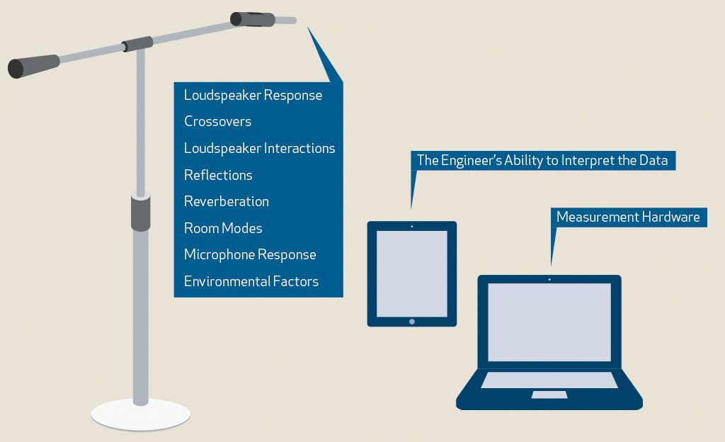
DIAGNOSIS 101
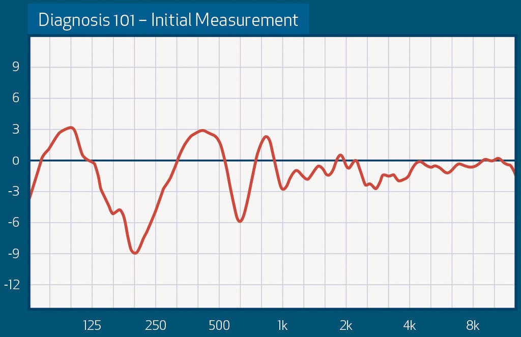
Let’s start by having a look at the above measurement, and asking the question: What would you do to this trace?
Would you:
- Start applying EQ to fix those big dips and peaks in the low mids.
- Begin pulling the PA apart — something is obviously broken or out of phase.
- Leave it alone, it’s probably a ground reflection.
- Nothing. How could I? I know nothing about what the measurement was taken of, and how, when, or where it was taken.
The only real answer is D, but if you answered C, then you’re halfway there. If you answered A or B — then you definitely need to read on!
To get better at measuring PAs the first thing you’ll need to do is re-visit your audio theory. Now don’t feel bad if your theory or measurement skills are lacking. I had a measurement system set up in front of big systems for a long time before I really knew what the heck I was doing with it, or more importantly, before I properly understood the complex audio world around me. What I soon discovered was that using a measurement system without knowledge of audio physics is like a chef trying to read an X-ray; you may be able to see that something looks broken or weird, but you’ll have no idea what you should do to fix it. And if you do try and fix it, you’re probably just going to make matters worse. Believe me, I’ve worn that chef’s hat more than once!
COMBING THROUGH IT
If you’re wondering where to start, a good place is sound source interactions and comb filters. Understanding what happens when sound sources interact with other sound sources, or with reflective surfaces, is absolutely crucial — not only from a system design and alignment perspective but a measurement perspective. Why? Because the vast majority of these interactions that show up as frequency response issues can’t be fixed with EQ, so when you see them on the screen you’ll need to know when to leave them alone.
Now most of you should know what a comb filter is, but when was the last time you really thought about it while looking at a measurement trace? The most common and usually the most severe comb filter is the one from the ground reflection, so we’ll focus on that first. The picture you judged earlier was a PA that has a reputation for excellent low-mid response, but with a severe ground reflection showing up in the measurement — any attempt to make that trace look better in the low mids would have been a mistake.
Using a measurement system without knowledge of audio physics is like a chef trying to read an X-ray
HE GREAT OUTDOORS
Now the fun part begins. Get out your measuring kit and let’s start with a couple of experiments. While this might sound like a bit of work, doing your own controlled experiments will teach you more in one afternoon than months of trying to learn on gigs, installations, or reading text books. Your measurement system is an invaluable tool in not only aligning and tuning systems but helping you learn.
Grab yourself a speaker. What type is not important, but if possible, use the same speaker you’ll be measuring in the field to start developing an idea of what that speaker should ‘look’ like.
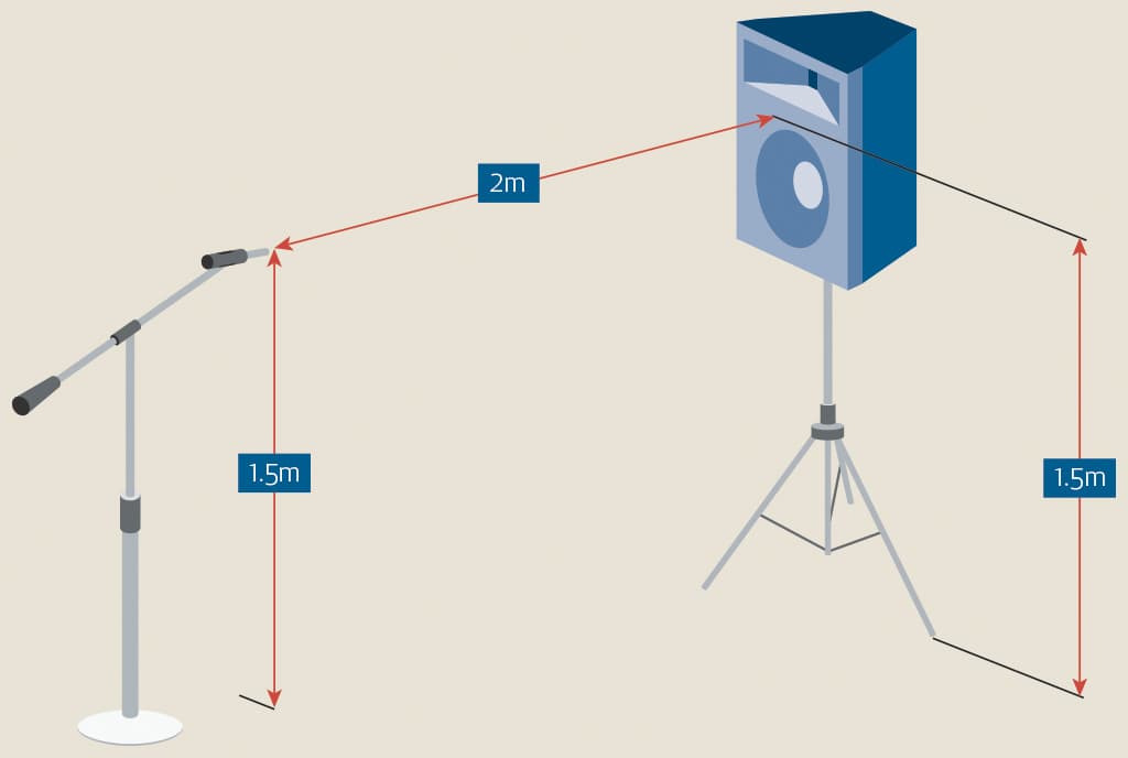
On a calm day, take one speaker outside and place it on concrete, or any other hard surface. Other hard reflective surfaces nearby are going to affect your results so put it as far away from walls and cars as the space allows. In a perfect world you’d be doing this in an open field, so the more space the better. Now if you’re using a relatively small speaker, put your speaker on the ground and the mic about two metres away. Place something under the back of the mic, so the actual capsule is as close to the ground as you can get while still pointing at the speaker. Then tilt the cabinet down a little so the mic is on axis.
This is closer than you’d measure in the real world, but the aim is to minimise the effect of any environmental and acoustic factors for the sake of the experiment. What you also need to note is that when you’re measuring too close to a speaker, the interaction between the drivers within the cabinet can heavily influence the measurement — so if something looks dramatically weird, move the mic back a little and see if it smooths out.
Now measure using the transfer function without too much smoothing. If you use too much smoothing you won’t properly see the comb filter; if you use too little, things can get confusing. I’ve found 1/12th is a good place to start, but 1/6th may give you a picture that’s a little easier to read. Wind can wreak havoc on your measurements, so use long averages of four or more seconds, and measure a few times in each position. If the measurement doesn’t change then you’re good to go. If it does, it’s best to try another day.
COMBING IN THE MIRROR
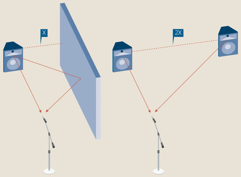
Once you have the first ‘ground’ trace stored and labelled, place the cabinet at a height of 1.5m and the mic on a stand at a height of 1.5m, and re-measure at the same distance. You should notice two things: the first is that the ground plane measurement is 6dB higher than the mic stand measurement; the second is that the mic stand measurement now has some big peaks and dips in the Low Frequency (LF) region.
First, let’s deal with the level change. No, somebody didn’t bump your preamp gain. This +6dB ‘for nothing’ is the same effect you get with a boundary mic where the direct sound and the reflected sound from the surface arrive essentially at the same time (and hence almost perfectly in phase at all frequencies). Because the mic is ‘on’ the surface, it’s the equivalent of placing the mic directly in the middle of two sources where you’d see a 6dB increase in pressure.
Think it should be 3dB? Well, I guess you just learnt something! This brings us to our next point about direct and reflected energy: whenever you have a sound source and a reflective surface, the sound field acts the same as it would if you had a ‘mirror image’ of that source on the other side of the surface, and the surface was removed (albeit with the effects of surface absorption applied to the mirrored image). Understanding this virtual mirror image (or image source modelling, as it’s known in acoustic simulation circles) is handy, because once you know how two sources interact you can then apply the same knowledge to a single sound source hitting a reflective surface. An acoustic two-for-one deal.
If you want some proof of this virtual mirror image phenomenon (and have the space to do it) grab an additional speaker of the same type and place both on the ground three metres apart. Place your mic directly in front of one of them (ie. on axis of one speaker only, not between the two) at the same distance away as the first experiment. The dips and peaks should appear in the same spot as your previous measurement with the ground reflection.
Remember: No surface is perfectly reflective, and loudspeaker coverage patterns are not omni-directional at all frequencies. This means that late arriving energy does not have the same frequency response or amplitude as the original signal and these combs may become more or less severe based on the situation, though the spacing of the peaks and dips should remain the same.
PEAKS & DIPS
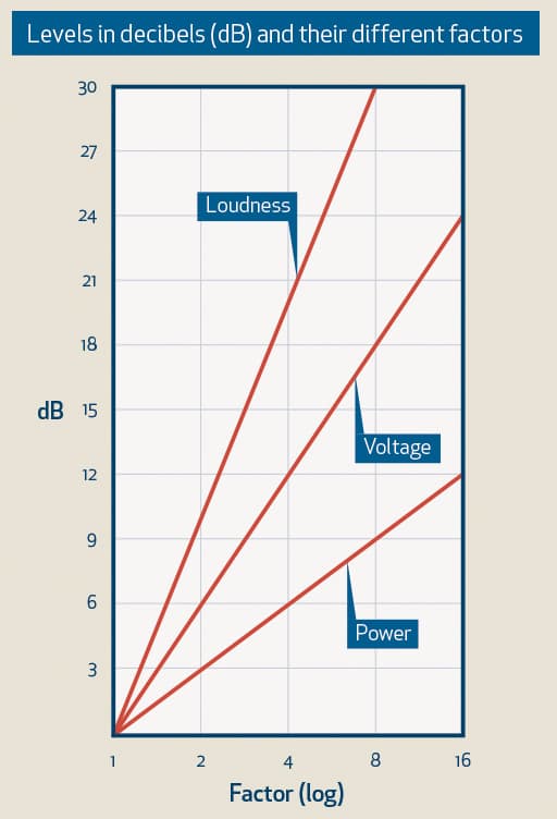
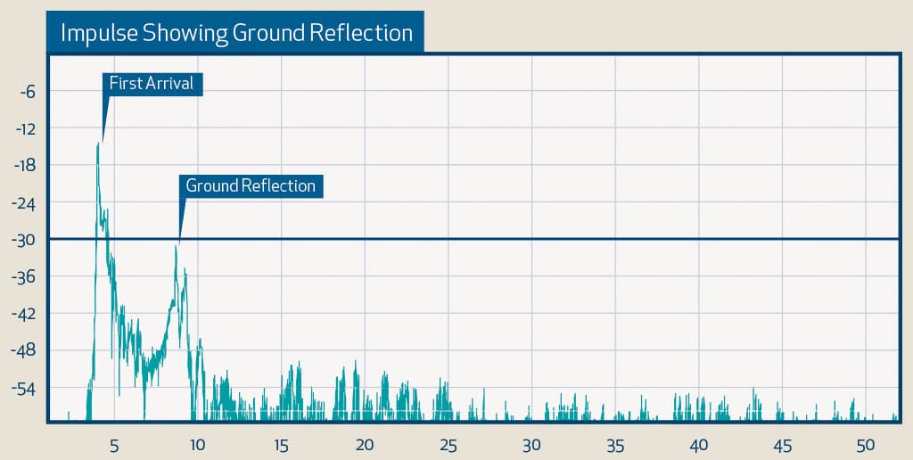
On to the peaks and dips. We know a comb filter is created by two identical sound sources arriving at a single point at different times. Here we have the direct sound from the loudspeaker arriving at the microphone position first, and the reflected sound from the ground arriving late. You should be able see the discrete late arrival by looking at the impulse response in your measurement system. The easiest way to find out where the combs occur is by measuring the time difference between the peaks of the impulse response, then using the formula 1/(2 x time difference between arrivals) to find the position of the first dip. Think back to what we know about sine waves. What happens when two perfect sine waves are out of phase? They cancel each other out completely. But when they’re perfectly in phase you can only ever gain 6dB, so the dips are always going to be easier to see than the peaks.
Let’s say the time difference is 5ms. We first translate that into seconds — i.e. 0.005s — then multiply it by two, to get 0.01s, then divide one by 0.01. The result should equal 100Hz. This is the frequency of the first dip you should see. There should then be a corresponding boost at 200Hz, a dip at 300Hz, a boost at 400Hz, another dip at 500Hz, and on it goes. When you think about this, the time period of 100Hz is 0.01 sec, so an arrival of 0.05 is completely out of phase at 100Hz and completely in phase at 200Hz, just one cycle late.
Now, since frequency lives in a logarithmic world and a comb filter appears in a linear fashion, as we move higher in frequency the peaks and dips get so close together that they effectively cancel each other out, and smoothing further hides the ripples. So usually once you get past the first three or so dips the comb gets very hard to see clearly. This is compounded by the fact that higher frequency information is often absorbed more effectively than lower frequencies, and higher frequencies are more directional (ie. if the speaker is facing straight forward, high frequencies don’t radiate into the ground as much as lower frequencies). In a nutshell, the comb effect becomes less severe as we move upwards in frequency.
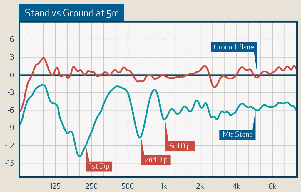
So take the number of the first dip we calculated, multiply it by three to find the second dip, and five to find the third dip. If you find these three dips in succession, there’s a good chance you’ve found yourself a comb filter.

TRACING ON PAPER
Back to the original, single-speaker setup. If you can’t wait until you have the time to do this experiment for yourself, then here’s a couple of measurements I took using a great sounding two-way speaker.
You can clearly see the ground plane measurement (6dB higher like we discussed) and then the measurement with the ground reflection. What you can see is that the bottom end appears to have high-passed and there’s now a large boost around 220Hz, then a dip just above 330Hz, then a peak around 440Hz and another dip at 550Hz. Now the first dip of the comb filter is actually centred around 110Hz, but the High Pass Filter (HPF) in the cabinet makes it a little hard to see, and it just appears like the HPF has been moved up. If you do the math, this is exactly where these comb filters should be occurring.
Here’s another one, this time with the same speaker and mic on the stands, but measured at five metres. For a 5m distance and 1.5m speaker/mic height, the initial comb should be very close to 200Hz, with the third and fifth dips around 600Hz and 1kHz, respectively.
Now some of you may ask, “Doesn’t the Time window get rid of late arriving energy in the measurement?” Well, unfortunately, this only works for higher frequencies. Once you move to lower frequencies (where these interactions have the most impact) the measurement system needs a long Time window to get enough resolution in the frequency domain. This means most of the reflections that do major damage still arrive within the Time window. Those of you that have ever worked with a single Time window (unlike the multi-Time window systems mainly used these days) will be very aware of this issue.
The ground reflection is no different to any other reflection, just that it’s the only one that will show up every time you are measuring when the mic is raised off the ground.
The theory is exactly the same for side walls, rear walls, ceilings, large objects, or any other surface that reflects the sound source back towards your microphone. So once you’ve mastered picking up on that ground reflection, stay outside and start setting up your speaker next to walls and other reflective surfaces and try to pick them up in the measurement too. First try the mic on the floor so the wall reflection is prominent, then take the mic off the ground so you’ve got both the wall and the ground reflection… Now take it inside where you not only have reflections, but room modes and reverberation to worry about! Getting complicated? Damn right! But hopefully this is starting to give you a picture of how much more there is to measurement than simply flattening the squiggly line.
In the next few articles, we’ll start looking at getting to know the speaker you are measuring and why this is important. As well as some tricks and tips on measuring in a reverberant environment; using that dreaded phase trace; and finally, putting it all together including tips on measurement settings, mic placement and EQ practices.




Dear Ewan McDonald,
do you have the Part 2 of this article?
Thank you very much!
I really enjoyed the practical explanations and even after 40 years in the field I feel the frustrations of speaker directions just recently I purchased the CLIO12 software and I think in my heart that it was unnecessary. I used 20 years with SPECTRA PLUS software looking for candles your second lesson.