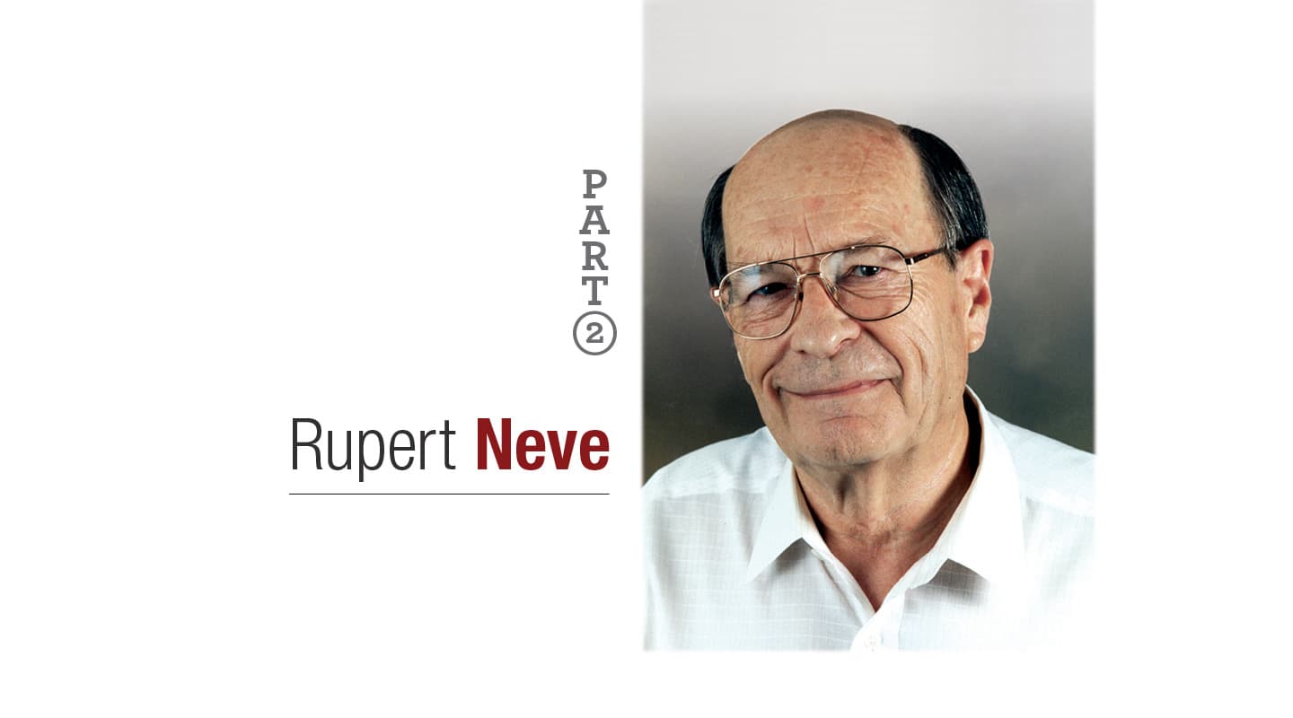
Rupert Neve Interview Part 2
Musicality, warmth, transparency... In the history of pro audio, one name has always been synonymous with these qualities. In part two of our three-part interview, Rupert Neve talks to Greg Simmons about cables, transformers, chip tweaks, and his designs for AMEKʼs System 9098 equipment.
Rupert Neve. The name is associated with some of the most cherished and long-lasting pro audio equipment ever made. In a world of low-cost digital equipment designed by mathematicians and accountants, it’s nice to know that some people still put sound quality ahead of the numbers.
Part One of our interview, published last issue, concluded with Rupert Neve commenting on how ‘knowledge’ can sometimes get in the way of progress: “The danger here is that the more qualified you are, the more you ‘know’ that something can’t be true, so you don’t believe it. Or you ‘know’ a design can’t be done, so you don’t try it. Ignorant idiots like me don’t know it can’t be done, so we have a go and it works.” Part Two follows on from this point…
Greg Simmons: The power of belief can be very influential, especially when you’ve got a strong theoretical background. For example, my electronics training taught me that different speaker cables won’t make any difference to the sound at all, provided their resistances and capacitances are sufficiently low enough. I firmly believed that for many years, and I think that belief prevented me from hearing any differences. Then one day, quite by accident, I noticed an undeniable difference while reviewing a pair of studio monitors. It shook the very foundations of my knowledge.
Rupert Neve: Well, do you know why the cable makes a difference?
GS: Low inductance seems to be a factor…
RN: I’m not an expert on this subject, but I do know one of the world’s top cable designers. He actually lives in Austin, Texas, not very far from me – an Englishman, by the way, but like me, he has traitored and come to the States to live! He tells me that it is to do with the design of the cable, the lay of the cable, the skin effect, and in the insulation of the cable – the dielectric constant – and things of this sort. They affect the sound quality in ways that were not thought possible before.
GS: In the hi-fi world, the dielectrics are one of the selling points of cables, whether they use air, Teflon, whatever…
RN: Well, I’m very cynical about a lot of things. I’d go so far as to say that Alexander Graham Bell [1] never had this problem, because a pair of wires spaced four inches apart with wooden spacers every six inches or whatever it was, is a 600 ohm impedance. This is where the old 600 ohm business came from. Now, you will never find a cable in a modern studio with anywhere near a 600 ohm impedance. So you’ve got things like impedance matching to take into account.
GS: We’re heading into transformer territory here…
RN: We must bear in mind that most modern cables have a natural impedance in the range of 100 ohms or less. So if you’ve got a reasonably long cable, like about 60 feet, that natural impedance starts to produce cable losses and reflections. Most present day studio equipment, which doesn’t use output transformers, usually has some poor little IC chip trying to drive that impedance. The manufacturers will say it can drive full output into 10,000 ohms, or 1000 ohms, or even 600 ohms. That’s all right on a test bench where you have no more than a foot or two of cable. But when you try driving a long cable, the chips fall flat on their faces. They go into wild slew rate distortion. They are not designed to drive low impedances between 75 and 100 ohms, which is what you’re now asking them to do. So on the output stages of my equipment, I use transformers with quite beefy power amplifiers to drive the line. [2] I have done this for many many years.
GS: How about a practical example?
RN: The first major AMEK 9098 console into the US is here in Nashville, and I’m here satisfying myself that all is as it should be. I am still delighted with it, because after passing the signal through many many different stages, we are still measuring at well over +20dBu output and, at 20kHz, a distortion percentage which is ridiculously low, like 0.002 to 0.003 percent. It varies a little bit from one channel to another, but all you can see in the residual is a little bit of third harmonic. That output will drive any length of cable.
GS: What about microphones, which often have to drive the longest leads of all? You can’t really put a beefy power amplifier inside a microphone.
RN: Well, a microphone cannot feed long cable lengths without audible degradation. Lengths of 80 feet or more, which are not uncommon in recording studios, can degrade performance noticeably. You can’t always shorten the length of the cable, but you can increase the power of the microphone signal before it drives that length of cable, by the use of a remote controlled preamp. It can be placed close to the microphone, and will put out a signal that is much better suited to driving the cable.
I’ve designed a remotely controlled microphone preamp for AMEK, the RCMA, which I loaned to some friends at the University of Texas. They have a wonderful concert hall. It is as large as the Royal Festival Hall in Britain, owned by the University – that’s the scale on which they do things here in the States. The actual cable length from the microphone on stage, through to the control room, is 1800 feet.
GS: 1800 feet? That’s over half a kilometre…
RN: Originally the microphones were feeding this length of cable directly, with a lot of loss. Microphones are not designed as power drivers for cable. I loaned them the RCMA, which was placed as close to the microphones as we could get it, and the difference was amazing. The sound is totally transparent – I’m trying to persuade them to buy one!
We measured the overall response, from the RCMA input through all that cable to the console’s line input, and we are still getting an 85kHz bandwidth. [3] It’s 3dB down at 85kHz!
GS: At 1800 feet away?
RN: That’s right. The RCMA has a 200kHz basic bandwidth – like my other designs – but the resultant response is a function of cable length.
Of course, sound quality is more than just frequency response. Other parameters, such as distortion, must also be considered. The RCMA will drive its full level output into any line, to beyond 100kHz, without high order distortion. All these things are very important, sonically. If you get everything right at the front end and get a good sound, it will actually reflect right throughout the system – even if it’s a digital system.

GS: The microphone inputs on the RCMA, and the 9098 range in general, don’t use transformers. Instead, they use something called a TLA, a ‘Transformer Like Amplifier’. What’s the idea behind this design?
RN: Input transformers are much more difficult than output transformers, because you can’t control the source from which they are being fed. With an output transformer, it is integrated with the line driving amplifier, and you can use tertiary feedback (from a tertiary winding on the transformer) to get a really immaculate performance. The transformer itself is included in the feedback loop, therefore, low frequency distortion due to core saturation is reduced in proportion to the feedback, typically 1000 times. High frequency losses and distortion are not so much a problem with a transformer, but you reduce those anyway.
With an input transformer, you are typically feeding it from another piece of studio equipment that might have a source impedance of about 50 or 60 ohms. You are feeding into a bridging input. You have to make sure that the inductance of the winding of the input transformer is sufficiently high not to produce any appreciable loading at the lowest frequency of interest. And that the core is not going to go anywhere near the point at which distortion becomes evident. To do that, you need a transformer that is physically very large…
GS: So the core doesn’t saturate?
RN: That’s right. It’s actually got to be a long way from saturating. With an output transformer, you can use a given size of transformer and take the core right up to the saturation point, and the feedback will make sure that there is no effect until you are actually getting into the clipping point.
GS: So things stay fairly linear as you go up the hysteresis curve…
RN: Yes, they do. But you can’t do that with an input transformer. You can’t control it with the source impedance, because that is unpredictable. You can’t include the input transformer in a feedback loop with the amplifier driving it, because that amplifier belongs to the output circuit of a different device, and if you bring that into the input circuit, then it is no longer a floating circuit. So the input transformer is much more difficult.
That’s why I use the TLA. It’s just an instrumentation amplifier, which is pretty standard, but I bootstrap the inputs to give each leg a very high impedance to ground. The two inputs are tied together with a 10k ohm resistor, which turns it into a bridging input. If you feed a signal between one leg and ground, and leave the other leg floating, you get no output, because the two inputs are now tied by a 10k ohm resistor, and in effect, they’re commoned. You have something like 15 Meg ohms input impedance between each leg and ground, and 10k ohms between the two legs. So the differential signal is down to about -60dB. The circuit behaves like a transformer.
That has huge implications for common mode. People quote common mode rejection on an amplifier and they virtually take the figures out of the IC data sheet. Common mode rejection by itself has very little value. If you could guarantee that every unwanted or interference signal always arrived in common mode, then, yes, it would have a lot of value because it would be rejected and you could go well over 100dB down. But unfortunately the only way of guaranteeing your signal always arrives in common mode is to short the two inputs together, and that is bad news for the signal! [Laughs]
GS: Defeats the purpose a bit!
RN: It does, rather… So you’ve got a differential amplifier, and you need to make sure that frequencies above audibility, where you are getting into high frequency interference, are effectively shorted together so that common mode interference is reduced. I use a little differential input coil for that, which also serves as a filter. It’s a little bifilar wound coil on a small toroid, one coil in series with each leg. It has a 3dB down point at 200kHz, so that up to 200kHz it is a true differential input. Above that, it’s like a brick wall and pulls everything into common mode, so that now the common mode performance of your amplifier really comes into play, and nothing gets through.
Now that is a Transformer Like Amplifier. It is a lot cheaper than a transformer, and it will allow you to go to the full limits of the amplifier. You can put a +26dBu signal differentially into any of these amplifiers and, it doesn’t really matter what frequency, you get extremely low distortion and noise and so on. You couldn’t do that with a transformer, without using a very large and expensive one.
GS: So you’ve made a circuit that mimics an input transformer, but avoids all the problems of input transformers…
RN: Yes. Mind you, to counter what I have been saying, if you look at the new System 9098 Limiter Compressor, you will find that it does have an input transformer…
GS: That was actually my next question. Why didn’t you use the TLA on that product?
RN: I can’t tell you very much about that, because it’s totally new and I don’t want to have everybody else rushing to do the same thing! But let me say, there are quite a few years of research gone into the transformer that does that. You will find that with +26dBu input at 20Hz, the distortion due to the transformer is only about 0.003 percent of that harmonic, right up to the top level that the amplifier will handle. That little transformer, and the circuitry that it works with, is better than the TLA – despite all that I’ve been saying about it. A little bit more expensive, but not much.

GS: From what I gather, you are a very good transformer designer.
RN: Well I grew up technically as a transformer designer. When you worked with valves, everything had to be transformer coupled. In the early ‘50s, I worked for Rediffusion in London. They were first class engineers and really correct in everything they did, second only to the BBC in their ‘correctness’. I learnt a huge amount from them. One day, the transformer king, the guy who did all their transformer designs, gave me a book on transformer design and said, “Here, this is for you”. I said, “But I don’t need a book on transformer design, you are the transformer designer”. He said, “Well I’m leaving, and I’m supposed to find a successor. So here is the book.” [Laughs] That book is still on my shelf, and I refer to it quite frequently.
Transformer design is a black art. No engineer wants to know about transformers. The department had about 35 engineers, and he was going around talking to them. Finally, in some desperation, he came to a relatively new boy, me, and said, “here you are”. I was 24 years old. He gave me the book and the telephone numbers of excellent transformer designers like Brian Savage – long since departed – who taught me a huge amount. Later in my career, I became chief engineer of a very small company manufacturing transformers, and enjoyed myself finding better results in more cost-effective ways.
GS: So you have made this Transformer Like Amplifier circuit, which I guess you could call a virtual transformer. That leads me to your Virtual Class A circuitry…
RN: Okay, well, from our earlier discussion on crossover distortion and Class B amplifier designs, you can see the background a bit more clearly. [4] Crossover distortion is not to be tolerated, yet almost every integrated circuit [IC] has a push/pull Class B or Class AB amplifier on the output. There are only one or two exceptions I have come across which have Class A output amplifiers. With any push/pull amplifier, there will be a point at which there’s a transition from the negative half cycle amplifier to the positive half cycle amplifier, or vice versa. Even if it isn’t a very obvious one, even if the amplifier is biased into Class A/B, that transition is enough to produce some high order harmonics. It is those high order harmonics that make the difference to the sound. They are the crossover distortion. So you say, “okay, so we don’t use integrated circuits”. Unfortunately, in a modern console, you don’t have many options. You cannot use valves for obvious reasons – there are far too many circuits required in the console. The 9098 console, for example, has 48 busses, four stereo busses, one LCRS bus and 16 auxiliary sends. Can you imagine the number of valve amplifiers required for each module?
GS: It would get very hot… Although maintenance would probably be easier, you’d just look for the tubes that aren’t lit up!
RN: Absolutely! But you’d also need a gigantic module, and size is a big problem. And then you go on to think, “what about transistors?” You can create transistor amplifiers anyway you like, yes, but to some extent the same argument applies. Transistor amplifiers occupy quite a lot larger space than an IC. They sound beautiful, the size of the device is much more satisfactory compared to valves, but they are very expensive to manufacture because of the huge amount of work putting together a large number of components. The component count, in other words, is very important.
So you must use ICs, but there are a number of dodges. First of all, where I can’t use a true Class A IC – as I say, there are only one or two that I know of, and they’re limited in the amount of load that they will feed – then I will use this offset technique. If you apply an offset bias of about a volt to the IC, you’ve shifted the crossover point. They are no longer working symmetrically. One half of the output stage is doing all of the work until you reach the point of the one volt peak signal level. You will find that comes to somewhere in the region of just below 0dBu output level. So at every level up to that point, there is no crossover distortion at all, because it is operating as a Class A amplifier.
GS: And above that point, it switches to Class B, push/pull operation?
RN: Yes, and you get normal IC performance. But the difference is, of course, if you don’t apply an offset bias, then it is always operating in Class B, and every time a signal crosses your zero crossing point, no matter how small it is, it is going to produce crossover distortion. In fact, the smaller the signal, the higher the percentage of crossover distortion, and it is with you all of the time. Once you displace it with an offset bias, you have no crossover distortion on small signals. You can displace it as much as you like, and right up to the point you’ve chosen, there is no crossover distortion. When you do hit crossover distortion, its percentage could be probably 10,000 times lower, depending upon the noise floor and where your crossover distortion was happening before.
GS: That’s because the signal amplitude at that point is much higher relative to the distortion level?
RN: That’s right. Now, because of the offset bias, one side will clip before the other, and you will lose about 1dB of headroom. But my argument is that a good engineer will not let his signal clip more than once a year, so the 1dB isn’t important! But he has no control over crossover distortion, which is happening all the time. So I’ll trade that 1dB of headroom for no crossover distortion.
GS: When you apply the bias to the chip, is it done by modifying the value of the individual supply rails, or is it applied to the chip somewhere else?
RN: You just apply a voltage bias to the non-inverting input. Instead of returning the DC path to your power supply’s zero volt rail, you return it to a new ‘zero’ rail which you create, that is actually a volt above or below the normal ground.
GS: That sounds like a good solution when using a chip. But don’t you also use discrete transistors in the Virtual Class A circuits?
RN: Yes, okay… Well now, with ICs, the size of the internal transistors is very small. The average audio IC will have somewhere between 25 and 30 actual devices inside the package. The junctions are so small that you have to watch things like heating. A single transient going up to a higher level, at perhaps a very short duration, will heat a junction momentarily, and that changes its transfer characteristic. The effect is very difficult to measure; in fact, I have just recently succeeded in measuring it. So what we do is make sure the IC does not have to feed a heavy load alone and unaided. And so, for output stages, I will always add a pair of output transistors to do the load driving.
GS: And that reduces the amount of current drawn through the chip, thereby keeping it cooler and maintaining a more constant transfer characteristic?
RN: Well, people can hear the difference between an IC amplifier and a discrete component amplifier. You get this effect, which I call a ‘squinching’ effect. It is hard to define, but it has got a particular IC sound to it. We use the IC. It is such a beautiful little beast, but we have to know its weaknesses and support it where it’s needed.
GS: So what about input circuits?
RN: On the inputs, of course, we use a standard IC that doesn’t have the appropriate low noise front end. So I’ll use a pair of low noise transistors on the front end to modify its performance.
GS: We’re approaching the end of Part Two of our interview. We spoke about digital audio in Part One, and you had some interesting things to say about it. There’s something I’ve been meaning to ask…
RN: Go ahead…
GS: Do you have any designs happening in the digital area yourself?
RN: Well, no, it would be premature to say that. I am not digital myself. I am now getting onto 72 years of age. I considered myself to be a good valve designer years ago, and then I had to migrate across and learn about semiconductors. I have no intention of learning it all over again for digital!
What is happening now is that we have some pretty wonderful designers around who are also prepared to listen. The trouble with a lot of designers, you know, is that they don’t listen. They think their maths books will give them all the answers. You do absolutely need to listen, and to be prepared to listen to what other people are saying, too. And then you will be able to come up with some really first class designs.
1 Alexander Graham Bell (1847-1922) is widely regarded as the inventor of the telephone. Bellʼs telephone line consisted of a pair of wires spaced four inches apart, which created a 600 ohm impedance. This impedance ʻstandardʼ found its way into equipment designed for early broadcast and music studios, although it has little relevance to the modern studio.
2 The ʻbeefy power amplifiersʼ are usually referred to as ʻline driving amplifiersʼ. They provide the signal to the transformer, which then passes it on to the line.
3 In Part One of this interview, Rupert discussed the need for wide bandwidth and his belief that audio equipment should be able to cleanly reproduce frequencies at least as high 75kHz.
4 Crossover distortion and its relation to Class B (or push/pull) amplifier circuits was discussed in Part One of this interview.









RESPONSES