Microphones: Comb Filtering 3
In the seventeenth instalment of this on-going series about microphones we finish our exploration of comb filtering with some everyday examples and solutions…
The previous two instalments of this series have explored the phenomenon of comb filtering, how it happens and what it does to the signals from our microphones. In this instalment we’re going to look at some typical comb filtering examples and what we can do to fix them.
Three typical comb filtering examples were given in the 15th instalment of this series. The first two showed how comb filtering occurs when close-miking guitar amplifiers, the third showed how multiple instances of comb filtering can occur when close-miking a drum kit. The comb filtering problems shown in these examples are not unique to guitar amplifiers or drum kits, of course. They apply to any situation where more than one mic is used to capture the same sound, or where one microphone captures two versions of the same sound (one direct and one reflected).
In all three of the previous examples comb filtering occurs because a sound has been combined with a delayed version of itself, resulting in a series of peaks and dips throughout the frequency response. We added frequency and amplitude values to some of those examples so that we could calculate the frequencies that would be affected by the peaks and dips of comb filtering, and then plotted their resulting frequency responses – invariably arriving at something like this:
…comb filtering occurs because a sound has been combined with a delayed version of itself
WHAT ABOUT LEVELS?
All of the comb filtering frequency response examples shown so far were based on worst-case theoretical scenarios that assumed the original sound and the delayed sound were combined at the same magnitudes, resulting in complete cancellation at fc (the fundamental cancellation frequency). That’s rarely the case in practice. If the two signals are not combined with the same magnitudes then the cancellations at fc and above will not be complete nulls, and the reinforcements below and above fc won’t reach the full +6dB – therefore the comb filtering effect is less significant. The greater the difference between the magnitudes of the two signals, the less significant the comb filtering will be.
The illustration above shows what happens at fc when the original signal (green) is combined with a delayed version of itself (blue) that has a lower magnitude than the original signal – as would be the case if the delayed signal had travelled further than the original signal (e.g. comparing a close mic with a distant mic on the same sound source). In this case, the original signal’s positive half-cycles reach +1 at the same time the delayed signal’s negative half-cycles reach -0.5, and vice versa. The resulting signal (yellow) is simply the addition of the original and delayed signal. If both signals had the same magnitude then the result would be complete cancellation, but that’s not what we see above.
The illustration above is for the same situation as the previous example but the frequency is now 2fc (two times fc) so the delay time is now equal to one full cycle rather than one half cycle. In this case, the original signal’s positive half-cycles reach +1 at the same time the delayed signal’s positive half-cycles reach +0.5, and vice versa. The resulting signal (yellow) is simply the addition of the original and delayed signal. The combined signal still shows reinforcement, but it is not as strong as shown in the examples in the previous two instalments.
The illustration below shows what the comb filtering looks like in this example. At the frequencies that cause cancellation (i.e. fc and all odd-numbered integer multiples of fc), when the original signal is at the peak of its positive half-cycle the delayed signal is at the peak of its negative half-cycle. The original signal has an amplitude of +1, while the delayed signal has an amplitude of -0.5. The resulting signal’s amplitude is +0.5 (+1 + -0.5), which is half the amplitude of the original signal. When converted to decibels this represents a decrease of -6dB. In other words, the cancellations will reach a maximum of -6dB rather than being complete nulls.
What about the reinforcements? At frequencies that reinforce (i.e. below fc and at all even-numbered integer multiples of fc), when the original signal as at the peak of its positive half-cycle so too is the delayed signal. The original signal has an amplitude of +1, and the delayed signal has an amplitude of +0.5. The resulting signal’s amplitude is +1.5, which is 1.5x higher than the original signal. When converted to decibels this represents an increase of +3.52dB. Therefore the reinforcements will reach a maximum of +3.52dB, rather than the +6dB seen in earlier examples where both signals had the same magnitude.
As shown above, we still see the familiar comb filtering shape but the peaks do not reach +6dB and the dips do not form complete nulls. It’s still going to cause the familiar comb filtering problems, but they won’t be as severe or as obvious. As we reduce the magnitude of the delayed signal the affect of the comb filtering becomes less obvious, eventually reaching a point where it’s not an audible problem – although at that level the contribution of the delayed signal to the mix might be so small that it’s not worth using anyway.
PRACTICAL EXAMPLES & SOLUTIONS
Now that we’ve seen what causes comb filtering and how it manifests in our signals, let’s return to those three practical situations we looked at earlier – the guitar amplifiers and the drum kit – and see what the comb filtering is doing. Once we understand those situations we can apply the same understanding to other audio situations.
We’ll start with the example given previously that uses two microphones on one amplifier, because it’s the easiest to see how we get an original and a delayed version of the same signal.
Two Mics, One Amplifier
Here’s the illustration for this example from the previous instalment, but with different distances than used earlier.
This is a classic miking set-up for electric guitar amplifiers with quad box speaker systems. It uses a Shure SM57 up close to one speaker cone (0.1m, as in the previous example) to capture grunt and bite, and a Neumann U87 at a placement and distance of 1m to capture the ensemble effect of multiple speaker cones working together. Let’s do the calculations used in the previous instalment to determine fc, starting with the PLD (Path Length Difference) and following with the ATD (Arrival Time Difference). The PLD is 0.9m (i.e. 1m – 0.1m), and that gives us a corresponding ATD of 0.00261 seconds (i.e. 0.9 / 344).
We’ll stick to integer values for the answers to the following fc calculations to allow some wriggle room for the inevitable rounding errors that occur when working with decimal values of distance and time…
PLD: fc = 344 / (2 x 0.9) = 344/1.8 = 191Hz
ATD: fc = 1 / (2 x 0.00261) = 1/0.00522 = 191Hz
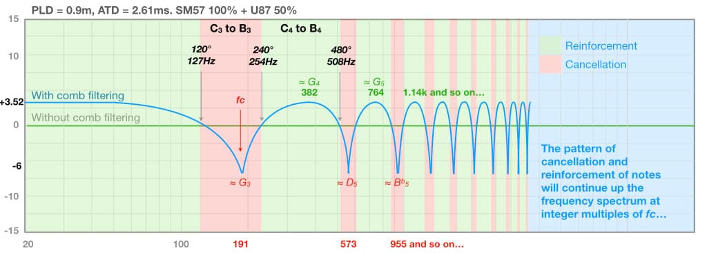
For this example fc is 191Hz, as confirmed by both calculations. It’s right between F#3/Gb3 (185Hz) and G3 (196Hz), and close enough to each to be a problem because the break-even frequencies will be 127Hz (120°) and 254Hz (240°) respectively – all notes that fall between 127Hz and 254Hz (i.e. from C3 to B3) will suffer cancellation in accordance with the comb filtering frequency response curve.
Cancellation will also occur at and close to all odd-numbered integer multiples of 191Hz (573Hz, 955Hz, 1.337kHz, etc.), and reinforcement will occur at all even-numbered integer multiples of 191Hz (382Hz, 764Hz, 1.14kHz, etc.), as shown below. Notes in the green areas will be reinforced, while notes in the red areas will be cancelled or reduced in level.
This is a classic miking set-up for electric guitar amplifiers with quad box speaker systems.
But what about the levels? If the signals from both microphones were mixed together at the same magnitudes, then the comb filtering would be as severe as shown in the illustration above. If they were mixed at different levels then the comb filtering won’t be as severe. For example, let’s say the Neumann U87’s signal was combined at 50% of the level of the Shure SM57. As we saw in an earlier example, in this situation the cancellations would only reach -6dB and the reinforcements will only reach +3.52dB. The resulting comb filtering response would look something like this:
Even when the delayed signal is mixed at 50% magnitude the comb filtering creates a significant change in the frequency response, meaning that the resulting signal will not sound like it did through either of the individual mics and, more importantly, it will not sound as the musician intended — the comb filtering is literally changing the levels of individual notes.
One solution to this problem, for recording at least, is to align the waveforms of the two signals in the DAW – otherwise known as time-alignment (as shown above). Slide the U87’s waveform along the time axis towards the left until it aligns with the SM57’s waveform. Zoom in to check that both signals start at the same time and that both signals cross the zero axis at the same time (to ensure there is no phase difference between them), and check that both signals have the same polarities at the same times as shown below.
The two signals should now add together with no comb filtering or polarity issues, allowing them to be blended together to create numerous tonalities and spatial possibilities. For example, the blend could favour the distant mic during rhythm/accompaniment parts to make the guitar feel a bit further back and behind other featured instruments, then changed to favour the close mic for moments that feature the guitar.
A more complex version of this time-alignment technique was used on the album Secret Samadhi (1997) for the band Live. A number of microphones were placed at different distances from the guitar amplifier, then each mic’s signal was timed-aligned (assumedly to the closest mic) and blended as desired to create a rich but singular guitar amplifier sound with many different tonal and spatial possibilities. [The song Lakini’s Juice provides a good example.]
Into The Concert Hall…
Let’s deviate from our three examples for a moment to see this microphone time-alignment technique used on a much larger scale…
Engineers who record classical, orchestral, chamber and choral music often use time-alignment with their microphones. In these situations the overall performance is usually captured by a main microphone array that is placed somewhere above and behind the conductor. It could be a stereo pair, or it could be a multiple microphone array intended to capture sound for an immersive/surround format. For this discussion we’ll keep it simple and stick to a main stereo pair. The placement above and behind the conductor puts the main stereo pair a number of metres away from the instruments, where it is intended to capture a balanced representation of the entire ensemble along with some of the room’s reverberation.
Instruments that are not captured loud enough or clear enough in the main stereo pair are given individual spot mics (i.e. close mics) that are mixed with the sound captured by the main stereo pair. The illustration below shows a spot mic being used to reinforce and/or clarify the sound of the flutes. To simplify this example we’ll use a coincident pair (e.g. XY, Blumlien, MS) as the main stereo pair, simply because it avoids ATDs between the mics in the main pair.
Engineers who record classical, orchestral, chamber and choral music often use time-alignment…
The considerable distance between the spot mic and the main stereo pair creates a large PLD and its associated ATD, and it is common practice to delay the spot mic to time-align it with the main stereo pair. This can be difficult to do because the waveform from the main stereo pair represents all of the music, and will therefore look very different to the spot mic’s waveform (which primarily represents the individual instrument it is aimed at). To solve this problem, prior to the performance a handclap or similar percussive sound is performed in front of each spot microphone and simultaneously recorded on the spot mic’s track and on the main stereo pair’s tracks. This provides a helpful visual cue for time-aligning the spot mic’s waveform with the main stereo pair’s waveform in the DAW, as shown below:
When widely spaced microphones are used as the main stereo pair (e.g. omnis spaced 50cm apart, aka ‘AB50’) and the spot microphone is significantly off-centre, as shown in the illustration below, the alignment handclap will not occur at precisely the same time in each channel of the main pair and it can be hard to decide which handclap to use for alignment purposes. Placing the spot mic’s handclap waveform in between the handclap waveforms shown in the main stereo pair’s tracks moves the spot-miked instrument to the centre of the stereo image and requires extreme panning to move it where it is supposed to be. It also introduces the possibility of two instances of comb filtering – one between the spot mic and the left mic of the main stereo pair, and one between the spot mic and the right mic of the main stereo pair.
This situation requires a more sophisticated solution. The spot mic signal is duplicated to create two identical tracks. One track is panned hard left and its handclap is aligned to the handclap in the left channel of the main pair, and the other track is panned hard right and its handclap is aligned to the handclap in the right channel of the main pair (as shown in the illustration below)
Keeping both spot mic tracks at the same level ensures that the spot mic’s signal appears in the correct place in the stereo image due to the time difference between the microphones, while preventing comb filtering with the individual mics in the main stereo pair.
The two versions of the spot mic signal might comb filter with each other when summed to mono, but in that case it means the two mics in the main stereo pair will also comb filter with each other when summed to mono because they’re the references that the spot mic signals were aligned to. The solution here is to correct the spacing of the main stereo pair, or, if it’s too late to do that, beat yourself up about it and remember to get it right next time.
Now, back to our previous three examples…
One Mic, One Amplifier
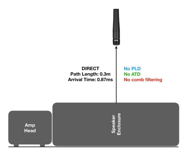
Let’s look at the first example from an earlier instalment of this series, reproduced below. It only uses one microphone, but a reflection off the floor creates a delayed version of the signal that combines with the direct signal at the microphone diaphragm – creating a comb filtering problem that we cannot fix with time-alignment because we don’t have access to the individual direct and reflected signals.
In this example a single microphone is placed 0.3m from the guitar amplifier but a reflection off the floor also reaches the microphone after travelling a total distance of 0.7m, creating a PLD of 0.4m – which corresponds to an ATD of 1.16ms. What is fc?
PLD: fc = 344/(2 x 0.4) = 344/(0.8) = 430Hz
ATD: fc = 1/(2 x 0.00116) = 1/0.00232 = 431Hz
Allowing for rounding errors due to the number of decimal places, both approaches give us essentially the same result: a fundamental cancellation frequency, fc, that we’ll call 430Hz. Cancellation will also occur at all odd-numbered integer multiples of 430Hz (1290Hz, 2150Hz, etc.), and reinforcement will occur at all even-numbered integer multiples of 430Hz (860Hz, 1720Hz, etc.).
[It’s worth noting that this problem can also occur in the previous ‘two mic’ guitar amplifier example, and cause considerable problems due to having potentially three different comb filtering situations: comb filtering due to the PLD between the microphones, comb filtering due to the floor reflection into the first microphone, and comb filtering due to the floor reflection into the second microphone.]
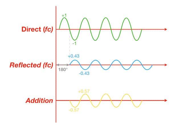
How bad will the comb filtering be in this example? The direct signal has traveled 0.3m to the microphone, while the reflected signal has traveled 0.7m to the microphone. According to the Inverse Square Law, the reflected signal will have 7.36dB less SPL than the direct signal. Here’s the maths for those interested…
ΔSPL = 20 x log(0.3/0.7) = -7.36dB
That’s equivalent to 43% of the magnitude of the direct signal. If the direct signal had a magnitude of 1, the reflected signal will have a magnitude of 0.43.
At the frequencies that cause cancellation (i.e. fc and all odd-numbered integer multiples of fc), when the direct signal is at the peak of its positive half-cycle the reflected signal is at the peak of its negative half-cycle. The direct signal has an amplitude of +1, while the reflected signal has an amplitude of -0.43. The resulting signal’s amplitude is +0.57 (+1 – -0.43), which is close to half the amplitude of the direct signal. When converted to decibels this represents a decrease of -4.88dB. In other words, the cancellations will reach a maximum of -4.88dB rather than being complete nulls.
What about the reinforcements? At frequencies that reinforce (i.e. all even-numbered integer multiples of fc), when the direct signal is at the peak of its positive half-cycle so too is the reflected signal. The direct signal has an amplitude of +1, and the reflected signal has an amplitude of +0.43. The resulting signal’s amplitude is +1.43, which is 1.43x higher than the original signal. When converted to decibels this represents an increase of +3.1dB. Therefore the reinforcements will reach a maximum of +3.1dB, rather than the +6dB seen in earlier examples where both signals have the same magnitude.
How bad will the comb filtering be in this example?
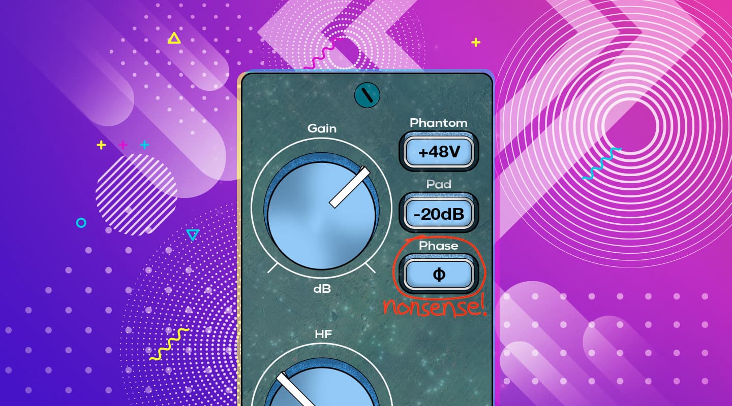
Because we do not have access to the two individual signals (direct and reflected), we cannot rely on time-alignment to fix this type of comb filtering problem. The incorrectly labelled ‘phase reverse’ (or similar nonsense) switch on our preamplifier won’t make any difference to the problem other than inverting the signal’s polarity.
The only solution here is to prevent it from happening in the first place. This can be done by placing absorptive material over the reflective surface – in this case, on the floor between the speaker enclosure and the microphone. The theoretical goal is to completely absorb the reflection, but it is often sufficient to absorb it enough to prevent it from causing noticeable comb filtering. Suitable absorptive materials include open cell foam (e.g. Sonex), compressed polyester fibre (e.g. Tontine Acoustisorb), crumpled blankets/duvets, cushions/pillows, and similar. To be effective the absorptive material typically needs to cover an area of at least 60cm x 60cm, centred over the reflection point.
Note that it is also possible for this problem to occur due to a reflection from a nearby wall or similar large reflective surface (this situation often happens when recording vocalists standing close to a wall, window or the reflective side of a studio baffle), and the same method of prevention applies.
Another way to prevent this problem is to change the position or placement of the sound source to increase the distance to nearby walls and other reflective surfaces. Also, if the speaker enclosure has a closed back it can be laid on its back, so the speakers face the ceiling, and miked from above (this might require the use of small blocks between the speaker box and floor to create enough clearance for the speaker connection). If placed in the middle of the room, the reflections from the walls and ceiling should arrive a considerable time after the direct sound and therefore have a considerably lower SPL – which is advantageous in minimising the audibility of comb filtering.
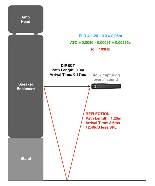
Alternatively, the speaker enclosure could be placed on a stand, raising the height and increasing the path length of the reflected sound, thereby reducing its SPL due to the longer distance and minimising the effect of the comb filtering. In the illustration below the speaker box has been raised by about 30cm to increase the path length, which lowers fc to 183Hz and gives the reflected energy 12.46dB less SPL than the direct sound.
This problem can also be solved by using a microphone with a bidirectional polar response, such as Royer’s R121 or BeyerDynamic’s M130 (shown below). Angling the microphone appropriately so that its side null is aimed at the reflection point will significantly reduce the amount of reflected signal captured by the microphone, thereby reducing the impact of the comb filtering. (We’ll be discussing how to use polar responses for minimising unwanted reflections in forthcoming instalments of this series.)
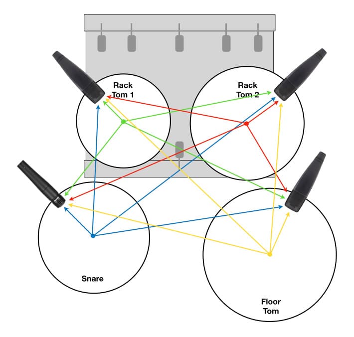
The illustration above is from the example shown in an earlier instalment, but with distances and calculations added. Using the centre of the snare drum as a reference point, we can see that the snare drum’s microphone is 18cm (0.18m) from the reference point. Rack Tom 1’s microphone is 45cm (0.45m) from the reference point, creating a PLD of 0.27m (0.45 – 0.18 = 0.27) between it and the snare microphone. Due to the Inverse Square Law the snare’s SPL at this microphone will be 8dB lower than at the snare mic. When added to the drum mix so that Rack Tom 1 was the same perceived level as the snare in the mix, this mic’s signal will create comb filtering with the snare mic’s signal with an fc of 637Hz and a dip of -4.4dB. This will be accompanied by dips of -4.4dB at all odd-numbered integer multiples of 637Hz, and peaks of +2.9dB at all even-numbered integer multiples of 637Hz. Similarly we can see that Rack Tom 2’s mic will create comb filtering at 291Hz with dips of -2.3dB and peaks of +1.8dB, and the Floor Tom’s mic will create comb filtering at 358Hz with dips of -2.8dB and peaks of +2.1dB. (Note that the decibel levels for the peaks and dips given above are theoretical approximates only based on the notion that each mic’s level has been adjusted so that the individual drums are all approximately the same perceived level in the drum mix.)
When auditioned on its own the snare sounds focused and punchy, but when the other mics are introduced to the drum mix the snare becomes blurred and spongy – which should be no surprise considering that every other mic in the drum mix is applying its own set of comb filtering dips and peaks to the snare sound, as shown in the previous examples. Superimposing all of these peaks and dips over the snare mic signal’s frequency response makes a real mess of the snare sound when it is heard as part of the drum mix. The small time delays blur or ‘soften’ the attack transients, while the cancellations from the comb filtering create holes in the frequency response and the reinforcements on either side of the cancellations make those holes seem deeper – just like a sponge.
We’ve focused on the snare drum mic for this example, but it’s important to note that every mic shown in the illustration creates comb filtering with every other mic shown in the illustration, and each comb filter occurs at the fc that is determined by the PLD between the mics. This means that the comb filtering that occurs to the snare mic’s signal due to the contribution of Rack Tom 1’s mic may not have the same fc as the comb filtering that occurs to Rack Tom 1’s mic due to the contribution of the snare mic. It’s possible that the mix of the four drum mics in this example could contain up to 12 individual comb filters (three per mic), each with its own fc and its own sets of peaks and dips. We’re approaching the point where Lo-Fi becomes No-Fi…
…the snare becomes blurred and spongy
Although not shown here, overhead mics can also introduce considerable comb filtering interactions with the close mics – especially if placed too low. Overheads can also create comb filtering between themselves if carelessly spaced apart, resulting in a phasey/swishing sound on cymbals that is easily identified when monitoring in mono.
Comb filtering is rarely a problem with a kick drum mic because a) it’s a sufficient distance from the other mics and b) it is often inside the kick drum and therefore isolated – except for spill from the snare bottom, which can be fixed with a low pass filter if problematic. If two kick mics are used on the same kick drum (typically one inside the shell facing where the beater hits the skin, and one just outside the shell) comb filtering between them can become a consideration, but this type of problem is easily solved with time-alignment as shown in the earlier example of two mics on the guitar amplifier because it is essentially the same problem: two mics at different distances from the sound source.
In contemporary popular music production the solution to the close-miked drum problems described above is to use noise gates when mixing live, and use automated mutes, editing and/or drum replacement when mixing in the studio. For other forms of music the solution is simple: use less mics on the drum kit. In situations where a more natural or accurate sound is required (e.g. orchestral, jazz and acoustic music) the entire drum kit is treated as a single instrument and captured with just one or two overhead mics, typically supported with a kick drum mic – not because a big thumping kick sound is required, but because the kick drum is considerably further from the overheads than the other drums and also aims outwards rather than upwards, so it is often poorly represented (at least tonally) relative to the drums and cymbals when captured by the overheads.
The illustration above shows a drum miking technique using a single overhead mic accompanied by a kick drum mic. A cardioid condenser is placed directly above the snare but angled to face somewhere between the floor tom and ride cymbal. Adjusting the angle of the microphone alters the balance across the drum kit, with the closer drums and cymbals arriving sufficiently off-axis to the mic’s cardioid polar response to be reduced by a dB or so — thereby balancing them against the more distant sounds from the floor tom and ride cymbal that arrive on-axis to the mic, while also maintaining a sufficiently detailed snare sound for brush work and similar. A ‘darker’ sounding SDC with good off-axis response, such as Milab’s VM44, works particularly well in this application. (We’ll be discussing how to use polar response for this kind of ‘mixing in the air’ in forthcoming instalments of this series.)
WHAT’S IT FOR?
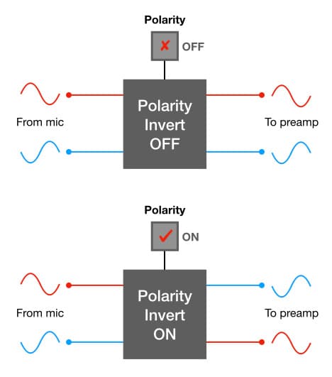
Throughout this and the previous two instalments of this series we’ve explored comb filtering in depth, and learnt that the switch on our preamps that’s incorrectly labelled ‘Phase Invert’, ‘Phase Reverse’ or similar nonsense is not the solution for phase-related issues because it does nothing to the signal’s phase – all it does is invert the signal’s polarity. So why is it there and when should we use it?
To minimise induced interference, professional audio equipment uses balanced differential lines for analogue audio interconnections. These typically rely on three conductors: one carries the correct polarity version of the signal (indicated with ‘+’), one carries an inverted polarity version of the signal (indicated with ‘-’), and one carries a 0 volt reference (aka ‘signal ground’) and/or provides a shield against induced interference by enclosing the other conductors inside a flexible tube made of wire mesh or foil and referred to, of course, as the shield.
[It’s worth noting that in the early days of the XLR connector the intention was to use a four-conductor cable: one conductor carried the correct polarity signal, one carried the inverted polarity signal, one carried the device’s 0 volt reference, and the other provided the shield that enveloped the other conductors and shunted any induced interference directly to electrical earth before it had a chance to enter the signal path. This allowed the device’s 0 volt reference to be kept separate from the shield and electrical earth, which was a good way of minimising the possibility of ground loops. The 3-pin XLR connector that has become the industry standard still has four separate connections — three pins plus a solder tab to extend the cable’s shield to the connector’s shell — and some cable manufacturers still make the ‘three conductors plus shield’ microphone cable required for this type of connection, such as Belden’s 9398. However, contemporary designs use a three-conductor cable — two inner conductors and a shield that also carries the circuit’s 0 volt reference — thereby introducing the potential (pun intended) for ground loops. This has become known historically as the ‘Pin One Problem’. Google it…]
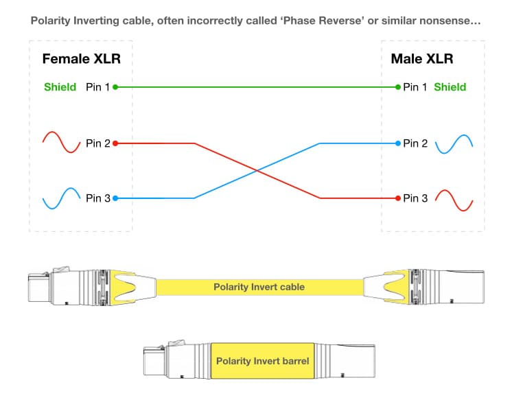
For many years before and after the introduction of the XLR connector there was no international standard detailing which pin carried the correct polarity signal and which pin carried the inverted polarity signal. Using the 3-pin XLR connector as an example, pin one was globally accepted as the shield and/or 0 volt signal reference but there was no standard defining which of the remaining two pins carried the correct polarity signal and which carried the inverted polarity signal. Some manufacturers and audio facilities settled on pin two for the correct polarity signal and pin three for the inverted polarity signal, and some settled on pin three for the correct polarity signal and pin two for the inverted polarity signal. This difference in wiring standards extended to microphone manufacturers, increasing the likelihood of polarity cancellation when microphones from different manufacturers were combined together. This wasn’t a problem for professional audio facilities where it was standard procedure for in-house technicians to check each new item of equipment and (if necessary) re-wire it to conform to their chosen standard, but it was a problem when equipment from different facilities was being combined – such as borrowing or hiring additional microphones or outboard equipment for a recording session or live performance. It was customary for audio facilities and services to have a number of incorrectly-named ‘Phase Reverse Leads’ (typically colour-coded yellow, and about 20cm long) or XLR barrels that connected pin two on the female XLR to pin three on the male XLR, and pin three on the female XLR to pin two on the male XLR. These short cables and barrels temporarily solved the polarity problem without altering the internal wiring of the equipment – which would not be acceptable with hired equipment.
The confusion between pin two and pin three on the XLR connector was finally settled in the early 1990s when the AES14 Standard locked-in the use of pin two for the correct polarity signal and pin three for the inverted polarity signal. Nowadays all professional audio manufacturers follow this standard. However, that doesn’t mean we no longer need that incorrectly-named ‘Phase Invert’ switch…
WHEN TO USE IT?
Before going any further, let’s give this seemingly obsolete yet remarkably useful switch a more appropriate name. We’ll call it the Polarity switch. Why? Because it affects the signal’s polarity. There’s no need for any further clarification in the name because a signal’s polarity can only have one of two states: correct or inverted. As long as we know which switch position is ‘inverted’ we’re good to go. So when should we use it?
The most obvious example is in the event of an incorrectly wired microphone lead, patch lead or patch bay. If it’s a balanced differential connection and it is wired incorrectly between pins two and three, or between the tip and the ring on a TRS jack or socket, the received signal will be inverted polarity. That’s exactly the sort of problem the Polarity switch was intended to fix.
Likewise if we are using two microphones with one on either side of a drum skin, or one in front and one behind a speaker box. In both of these cases, the sound captured by one of the mics will be in the opposited polarity to the sound captured by the other mic. More about that situation in a moment…
A less obvious situation is when you are combining two versions of the same sound, one from a pick-up and one from a microphone. For example, combining the sound from an acoustic guitar’s pickup with the sound from a mic in front of it. The wiring of the pick-up and the use of a DI box in the signal path both introduce the possibility for a polarity difference between the pick-up’s signal and the microphone’s signal.
The same situation exists when combining a DI signal from an electric bass guitar with the signal from a microphone placed in front of the bass guitar’s amplifier, and also when taking a direct output from an instrument amplifier and combining it with a microphone placed in front of the amplifier or the instrument itself. In all of these situations it is worth changing the polarity of one of the two signals and alternating between both versions to see which provides the best sounding result. But wait, there’s more…
Combining the signal from a pick-up (via a DI box or amplifier direct output) with the signal from a microphone placed in front of the instrument or amplifier also introduces the possibility of a time delay between the two signals, because the distance between the microphone and instrument or speaker will invariably be greater than the distance between the instrument’s strings and the pick-up. This type of problem is easily solved in recording situations by using the time-alignment methods described earlier in this instalment. In sound reinforcement situations we have to rely on polarity inversion and perhaps a sample delay if using a digital console. More about that below…
ABOVE, BELOW, IN FRONT, BEHIND…
Let’s finish this exploration of polarity, phase and comb filtering with some common miking practices that create a combination of polarity and comb filtering problems, and require the use of polarity inversion and time-alignment to do properly.
Front & Back Amp Miking
Putting mics in front and behind a speaker enclosure that has an open back, such as a Roland Jazz Chorus combo amplifier, is an open invitation for polarity and comb filtering problems. Why? Because the sound emanating from the rear of the speakers is in the opposite polarity to the sound emanating from the front of the speakers. Also, the mic at the rear will almost certainly be a different distance from the speakers than the mic at the front, which means there will be an ATD (Arrival Time Difference) between the front and rear mic signals. When the mic signals are mixed together there will be cancellation due to the polarity difference between them, and comb filtering due to the ATD between them. The solution requires a combination of polarity inversion and time-alignment, as shown in the illustration below.
We must invert the polarity of the rear mic’s signal to put it into the same polarity as the front mic’s signal, and then we must time-align it with the front mic’s signal.
It’s a relatively simple process in the recording studio. For sound reinforcement applications the polarity is the most important part to get right. The time delay can be taken of by careful placement of the rear mic, ensuring it is the same distance from the speakers as the front mic to minimise the possibility of an ATD.
Now let’s look at something that’s not so simple…
Snare Top & Snare Bottom
In many genres of popular music it’s common to use two mics on the snare drum. One mic is aimed at the top skin (aka the batter head) and intended to capture the overall sound of the drum – including its fundamental note and harmonics/overtones, the player’s articulation (i.e. attack of the stick on the skin), rimshots, side sticks and brushes. This ‘snare top’ microphone placement usually captures enough of the sound of the snares vibrating against the bottom skin (aka the resonant head) to represent the entire sound of the snare drum – especially when using shells of 11.4cm (4.5 inches) or less.
When using shells deeper than about 17.8cm (7 inches) it can be difficult to capture enough of the sound of the snares with just a snare top mic. The deeper shell gives more body and fullness to the tuned part of the snare sound (i.e. the note from the top skin), thereby reinforcing its level in the snare top mic. At the same time, however, the deeper shell moves the snares further away from the snare top mic (compared to a shallower shell) which makes them marginally softer and duller. The result is a more subdued contribution from the snares and an overall ‘darker’ snare drum sound. If that’s not the desired sound for the music it can lead to excessive high frequency EQ boosting in an attempt to create a brighter and snappier snare sound – which has the unwanted side-effects of exaggerating spill from the hi-hat and cymbals, making rimshots and side sticks sound ‘clacky’, and bringing a ‘harsh’ and ‘scratchy’ tonality to brushes. To avoid these EQ-related problems a mic is placed underneath the snare drum specifically to capture the sound of the snares. Not surprisingly, it’s referred to as the ‘snare bottom’ mic.
The intention is to combine the snare top mic and snare bottom mic signals to create a brighter and snappier snare drum sound without requiring excessive boosting of the high frequencies and all of the associated problems described above. Although we like to think of each mic as capturing only its intended sound, the reality is that each mic will capture considerable levels of sound from both skins (which is, of course, why we often don’t need to use a snare bottom mic).
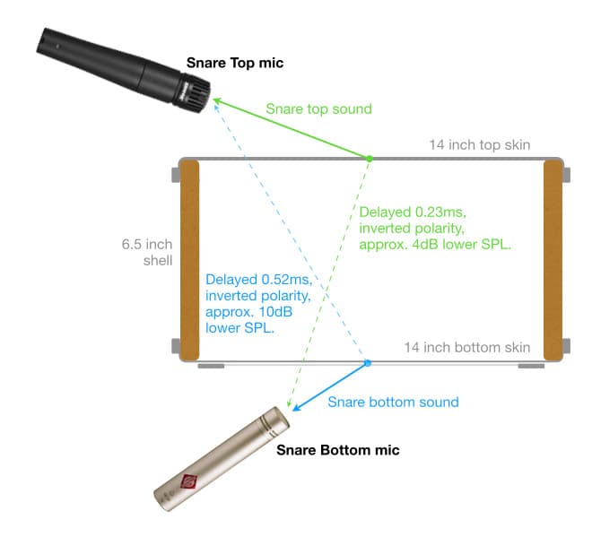
The illustration above shows a typical snare top and snare bottom miking scenario. The sound of the top skin goes directly into the snare top mic (green arrow), but also spills into the snare bottom mic (dotted green arrow). The spill into the snare bottom mic is an inverted polarity version of the sound going into the snare top mic and, due to the longer distance it travels, it arrives at the snare bottom mic a short time after it arrives at the snare top mic and thereby creates an ATD between the mics. Likewise, the sound of the bottom skin and snares goes directly into the snare bottom mic (blue arrow) but an inverted polarity version of it goes into the snare top microphone (dotted blue arrow) along with its own ATD.
When the top and bottom mics are mixed together we end up with cancellation due to the polarity differences between the two mic signals, and multiple instances of comb filtering due to the ATDs. The solution requires polarity inversion and time-alignment as shown earlier for the combo amp example, but, unlike the combo amp example, in this case we have two sound sources (top skin and bottom skin) creating two different instances of comb filtering, and that means we have to make an aesthetic choice between two different time-alignment solutions – we either align the spill in the snare bottom mic with the note of the top skin, or we align the spill in the snare top mic’s signal with the sound of the snares. This is discussed in detail at the end of this instalment (scroll down to ‘Making Great + Great = Great’).
CONCLUSION
In this and the previous two instalments we’ve taken a deep dive into polarity, phase and comb filtering as they apply to microphone use and placement. We’ve discussed the very important difference between polarity and phase, explored theoretical and practical examples of polarity and phase problems, seen the causes of comb filtering and how to fix them, and learnt why the terms ‘Phase Reverse’ and ‘Phase Invert’ (as commonly seen on mic preamps and channel strips) are nonsense. Whether or not you’ve understood the mathematics used in the examples is not important; what really matters is that you’re aware of polarity and phase problems, the differences between them, how to anticipate and/or identify them, and how to solve or prevent them.
Polarity is always a problem when miking something from both sides – such as top and bottom of a drum skin, or front and back of an instrument speaker. It is also a potential problem to be aware when we are combining a pick-up sound (via a DI box or similar) with a miked version of the same instrument or its instrument amplifier.
Comb filtering is a potential problem whenever we are combining a signal with a delayed version of itself. The range of human hearing is said to be 20Hz to 20kHz, so any comb filter with an fc between 20Hz and 20kHz will land within the range of human hearing and is therefore a potential problem. An fc of 20Hz requires a delay of 25ms (0.025s), and delay times of 25ms or longer are generally perceived as spatial effects (e.g. ambience, echos) rather than tonality problems. Similarly, an fc of 20kHz requires a delay of 25us (0.000025s); a delay time of 25us or less is going to cause comb filtering well above the capabilities of human hearing and can be considered irrelevant – unless we are capturing sounds with ultrasonic content and pitch-shifting them down to create sound effects. Delay times that fall in the range between 25ms and 25us create fcs between 20Hz and 20kHz, and we should always be aware of the possibility of comb filtering in those situations. Delay times longer than 25ms or shorter than 25us are probably not worth worrying about in terms of comb filtering…
Polarity is an amplitude-based parameter with only two states: correct and inverted. The Polarity switch offers an amplitude-based solution for polarity problems. Phase is a time-based parameter with infinitely variable positions, and time-alignment and/or microphone placement are the time-based solutions for phase problems. To reiterate something from an earlier instalment: using an amplitude-based solution (the Polarity switch) to fix a time-based problem (comb filtering) is like using SCUBA gear to go skydiving – you’re diving, but you’re using the wrong tools.
So remember: use the Polarity switch for polarity problems, use time-alignment and/or microphone placement to solve phase and comb filtering problems, and use both solutions when you’ve got both problems at the same time (e.g. snare top/bottom, amplifier front/back, etc.).
In the next instalment we’re going to take a short break from the maths and physics and look at polar responses. It’s only going to be a short break, however, because the inescapable reality is that audio engineering is grounded in maths and physics. If we want to understand how to use polar responses properly and effectively then we’re going to need to get, er, ‘physics-al’…
The solution for the theoretical example shown above is simple: use the Polarity switch on one of the two mics. The Polarity switch is also part of the solution to the practical problem of using a snare top mic and snare bottom mic. There’s still the comb filtering problem, and, as we’ve seen in the previous two instalments, changing the polarity doesn’t stop or fix comb filtering – it only changes the comb filtering’s tonal character by turning the cancellations into reinforcements and the reinforcements into cancellations. One version might be sonically and/or musically more acceptable than the other, but both versions are compromises and neither is a solution.
Comb Filtering Problem
Although the snare drum has two skins, only the top skin is hit with a stick. It is thicker and stronger than the bottom skin, and its tuning determines the snare drum’s fundamental note.
The bottom skin is made from a much thinner and lighter material than the top skin, because it’s intended for sympathetic resonance rather than being hit with a stick. It’s tuned to resonate with the top skin and enrich the overall drum sound, while extending or reducing the sustain (depending on its tuning) and also serving as a membrane to radiate the sound of the snares vibrating against it that creates the characteristic ‘snare drum’ sound. As sound engineers we’re primarily interested in capturing the sounds of the snare drum – the tuning and sustain are up to the drummer, of course.
Both skins play equally important roles, each worthy of its own microphone – but giving each skin its own microphone is where the comb filtering problems begin because each mic unavoidably captures spill (i.e. unwanted sounds) from the other skin. The snare top mic captures the intended top skin sounds along with unintended spill from the bottom skin, and the snare bottom mic captures the intended sounds of the bottom skin and snares along with unintended spill from the top skin. Because each mic is a different distance from each skin there will be different PLDs between the mics and the skins, and because each mic is capturing sounds from each skin those PLDs become ATDs between the two mic signals, as shown in the illustration below. When the two mic signals are mixed together the ATDs create comb filtering.
The illustration above shows the cause of the polarity and comb-filtering problems, but the mics are placed in positions that would be ridiculous in practice, so let’s look at a practical and typical miking placement. For this example we’ll use a Shure SM57 for snare top and a Neumann KM184 for snare bottom, simply because they are very common choices for this application.
We’ll use a 14 inch diameter snare drum, the kind that is usually tuned somewhere between 164Hz (E3) and 233Hz (A#3). It has a 6.5 inch shell that’s a little too deep for the chosen snare top mic to capture the brightness and ‘snap’ of the snares to our satisfaction – which is not surprising considering a) the snare top mic in this example is a cardioid dynamic and therefore not known for an extended high frequency response, b) the sound of the snares is arriving from about 40° off-axis, and c) the distance from the snares to this mic is considerably further than the distance from the top skin to this mic, so the sound of the snares will be considerably lower in level in this mic compared to the level of sound of the top skin.
As a result, the sound of the snares is not sufficiently represented in the sound captured by the snare top mic alone. To overcome this problem we’ve added the snare bottom mic – perhaps over-compensating by putting a bright microphone like the KM184 up close to a bright sound source. We’re certainly going to capture the sound of the snares with plenty of high frequency content, probably much more than we need, but cutting the high frequencies to control any exaggerated brightness might prove serendipitous by reducing the audibility of squeaks and creaks from the kick pedal, the hi-hats pedal, and the drummer’s leather shoes if it’s a formal event requiring the musicians to dress appropriately.
Mic choices aside, even if each mic sounds very good on its own we’ll find that mixing them together does not create the anticipated ‘product-exceeds-the-sums’ synergism because each mic is capturing some of the other mic’s signal. Combining them together creates overall cancellation due to opposing polarities, and comb filtering due to ATDs. Let’s look at how the sound of each skin is captured by each mic…
Top Skin Capture
The illustration below shows how the sound of the snare’s top skin is captured by the snare top mic and the snare bottom mic. We’ll use the centre of each skin as reference points, and we’ll conveniently ignore any level loss of the spill due to passing through the bottom skin and also due to arriving off-axis to the bottom mic.
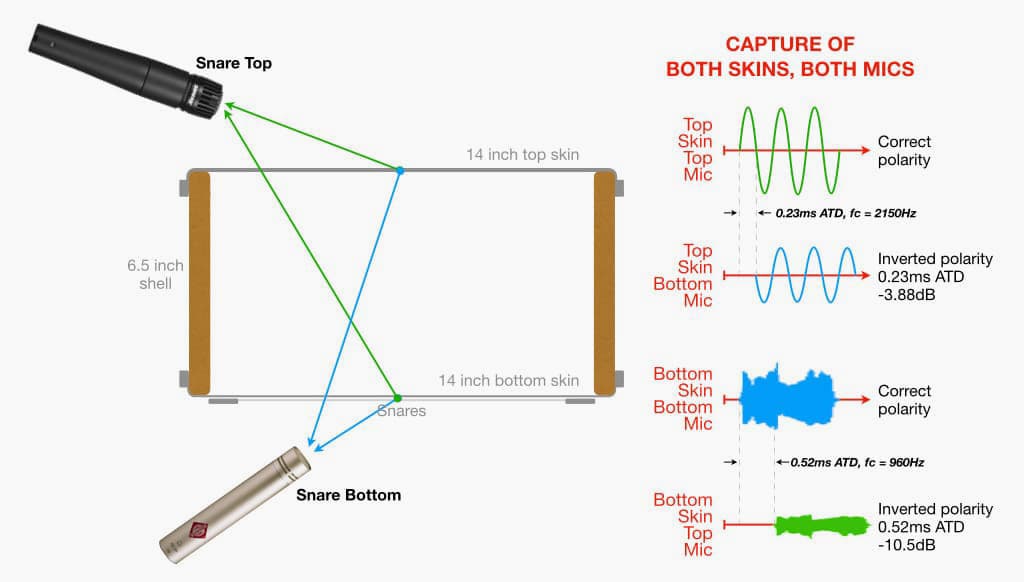
The snare top mic captures the sound emanating from above the top skin as shown with the green arrow and represented by the green waveform on the right. We’ll call that the ‘correct polarity’ version of the top skin’s sound because it’s the one radiating out from the drum and is also the version the drummer hears. In this example it travels 14.2cm (0.142m) from the centre of the top skin to the snare top mic.
The snare bottom mic captures the sound emanating from below the top skin, as shown with the blue arrow and represented by the blue waveform on the right. It’s an inverted polarity version of the signal captured by the snare top microphone because it emanates from the other side of the top skin. In this example it travels 22.2cm (0.222m) from the centre of the top skin to the snare bottom mic and loses 3.88dB of SPL along the way, creating a PLD of 8cm (0.08m) with a corresponding ATD of 0.23ms that results in comb filtering with an fc of 2150Hz. We can consider this to be ‘spill’ because a) it is not part of the bottom skin’s sound that the snare bottom mic is intended to capture, and b) having it in the snare bottom mic’s signal will create polarity and comb filtering problems when it is mixed with the snare top mic’s signal – which is not beneficial to the desired sound.
Bottom Skin & Snares Capture
The illustration below shows how the sound of the bottom skin and snares is captured by the snare top mic and snare bottom mic. Again, we’ll use the centre of each skin as reference points and conveniently ignore any level loss of the spill due to passing through the top skin and also due to arriving off-axis to the top mic.
The snare bottom mic captures the sound emanating from below the bottom skin as shown with the blue arrow and represented by the blue waveform on the right. We’ll call that the ‘correct polarity’ version of the bottom skin and snares’ sound because it’s the one radiating out from the drum. In this example it travels 7.6cm (0.076m) from the centre of the bottom skin to the snare bottom mic.
The snare top mic captures the sound emanating from above the bottom skin, as shown with the green arrow and represented by the green waveform on the right. It’s an inverted polarity version of the signal captured by the snare bottom microphone because it emanates from the other side of the bottom skin. In this example it travels 25.5cm (0.255m) from the centre of the bottom skin to the snare top mic and loses 10.5dB of SPL along the way, creating a PLD of 17.9cm (0.179m) with a corresponding ATD of 0.52ms that results in comb filtering with an fc of 960Hz. We can consider this to be ‘spill’ because a) it is not part of the top skin’s sound that the snare top mic is intended to capture, and b) having it in the snare top mic’s signal will create polarity and comb filtering problems when it is mixed with the snare bottom mic’s signal – which is not beneficial to the desired sound.
Great + Great ≠ Great
Each mic might sound ‘great’ when monitored individually, but with all of this polarity inversion and comb filtering going on it should be no surprise that the result doesn’t sound ‘great’ when the two mics are added together. How can we combine these two ‘great’ mic signals to create a solid snare drum sound that retains all the body and punch captured by the snare top mic and the snap and brightness of the snares captured by the snare bottom mic?
The solution has two parts, and the first part is easy: invert the polarity of one of the mics. Inverting the polarity of either mic will solve the polarity problem, but if we invert the polarity of the snare top mic it’s going to be very disorienting for a drummer on stage who is hearing the direct (i.e. acoustic) sound from the snare top in one polarity and the snare top mic’s sound through the drum fill in the opposite polarity. Combining a signal with an inverted polarity version of itself is exactly how noise-cancelling headphones work, but in this case it creates a snare-cancelling system that’s really going to mess with the drummer’s playing dynamics. Likewise if we’re recording a drummer who is monitoring with headphones, unless those headphones have very high isolation of external sounds (e.g. Direct Sound EX-29 Plus or similar). To avoid this problem we should default to inverting the polarity of the snare bottom mic whenever the drummer is monitoring the miked snare sound while playing. If you’re mixing in a multitrack studio situation and find that inverting the polarity of the snare bottom mic adversely affects the kick drum sound, try inverting the polarity of the snare top mic instead but check how it affects the sound of other parts of the drum kit that spill into the snare top mic – particularly the hi-hat.
The second part of the solution is not so easy: we have to time-align the two mic signals. If we’re using a DAW we can slide the snare bottom mic’s waveform to the left to align it with the snare top mic’s waveform. This is easier said than done because the waveforms look very different. Thankfully the snare is a percussive instrument, so if the attack of both waveforms start at the same time there’s a good chance that they’re aligned and will be reinforcing each other if you’ve got the polarities correct. [Here’s a trick to simplify the alignment process: immediately before recording, but after all the mic placements are finalised, record a few hits of the snare drum with the snares turned off. This will provide a cleaner waveform of the top skin’s spill into the snare bottom mic and bring more certainty to the alignment process.]
Astute readers may have noticed an interesting dilemma – the ATD in the top skin’s capture is different to the ATD in the bottom skin’s capture, as shown in the illustration above. This is due to the non-symmetrical placement of the mics on either side of the drum, and because both skins are individual sound sources. If we align the top skin waveforms captured by both mics it means the waveforms of the snares captured by both mics will not be aligned, and vice versa. Which one do we favour? We’ll come back to that in a moment… This is where the SPL values and ATD values in the illustrations above become helpful.
The top skin waveforms have an ATD of 0.23ms, which will cause comb filtering of the top skin’s sound with an fc of 2150Hz upwards. Considering that the top skin is rarely tuned higher than 233Hz (A#3), we’re probably not going to be too worried about the effects of comb filtering beginning at 2150Hz – that’s marginally higher than the top skin’s 9th harmonic (2097Hz). Also, we know that the level of the spill from the top skin into the snare bottom mic is 3.88dB lower than it is into the snare top mic. How loud would the snare bottom mic’s signal need to be in the mix before it caused an audible comb filtering problem with the snare top mic’s signal?
The 3:1 rule (discussed in a forthcoming instalment of this series) tells us that if the spill is 9.5dB or lower than the direct sound then it probably won’t cause any significant audible issues – including comb filtering. So, if the snare bottom mic was turned up in the mix to have a similar overall perceived level as the snare top mic, the top skin’s spill will only be about 3.88dB lower than snare top mic’s sound – which might be problematic if we’re worried about the 9th harmonic and above. It’s highly unlikely that a snare bottom mic is ever used in a mix at the same perceived level as the snare top mic; its typically 6dB or lower than the snare top mic, so it’s unlikely that comb filtering is going to be a problem for the top skin’s sound. What about the polarity? If the snare was tuned to 233Hz (A#3) its note would have a period of 4.2ms. An ATD of 0.23ms represents a phase shift of about 19.3° at 233Hz, meaning polarity cancellation is still going to be a big issue (the break-even phase shift is 120° as discussed in the previous two instalments), and therefore we’ll definitely need to invert the polarity of one of the two mics to avoid cancellation of the snare’s lower frequencies. As mentioned above, the snare bottom mic is a good default choice for polarity inversion.
Now that we’ve established that time-aligning the top skin waveforms won’t make much difference to the combined top skin’s sound, let’s look at the bottom skin waveforms…
The bottom skin waveforms have an ATD of 0.52ms. When the snare bottom mic’s signal is mixed with the snare top mic’s signal this ATD will cause comb filtering with an fc of 960Hz upwards. Anyone who has EQ’d a snare drum will know the importance of this part of the frequency range – it’s definitely not an area we want to have the peaks and dips of comb filtering running through.
We know that the level of the spill from the bottom skin and snares into the snare top mic is at least 10.5dB lower than its level into the snare bottom mic, supposedly satisfying the 3:1 rule. However, we also know that the snare bottom mic’s signal is usually not very loud in the mix relative to the snare top mic, thereby making the spill from the bottom skin and snares into the snare top mic’s signal more significant in terms of comb filtering. This provides a good argument for aligning the waveform of the snares in the snare bottom mic’s signal with the waveform of the snares spill in the snare top mic’s waveform. If we do that, we’ll be delaying the top skin’s waveform by 0.52ms. If it was tuned to 233Hz (A#3) a shift of 0.52ms would represent a phase shift of 43° between the top skin’s waveforms (i.e. snare top mic signal and spill from the top skin into the snare bottom mic’s signal), which is still not enough to prevent any significant cancellation of the fundamental note so polarity inversion will still be required.
What Does It All Mean?
What can we deduce from all of this theoretical meandering? We know there’ll be a polarity issue but that’s easily solved with the Polarity switch. What about those different comb filtering frequencies? As shown in the two illustrations above, the spill from the top skin into the snare bottom mic creates comb filtering at 2150Hz and the spill from the bottom skin into the snare top mic creates comb filtering at 960Hz. We can fix one of those with time-alignment, but not both. This is where we have to make an aesthetic decision…
If we are in a studio mixing situation using a DAW it’s easy to slide the waveforms to align the top skin and its spill into the snare bottom mic, or the bottom skin and its spill into the snare top mic, or anywhere in between those two options. We have the freedom to choose whichever tonality best serves the music.
We can’t use that approach in a sound reinforcement situation because we can’t move anything forward in time (i.e. sliding to the left on the DAW screen). However, if we’re using a digital mixing console that has a sample delay on each mic input we can delay the snare top mic until it sounds right when mixed with the snare bottom mic. In the example above the ATD for the top skin’s spill into the snare bottom mic was 0.23ms – that’s 0.00023 seconds, which is equivalent to 11 samples at 48k sampling rate. If we delay the snare top mic’s signal by 0.00023 seconds, we’ll bring it in time with the top skin’s spill into the snare bottom mic. A delay of 0.00023 seconds is equivalent to moving the drum fill 8cm (i.e. the distance of the PLD) further from the drummer, or moving the drummer’s ears 8cm further from the snare drum; a delay that short will almost certainly be irrelevant to the drummer from a performance point of view, but it could make a big improvement to the snare sound heard by the audience and by the drummer through the drum fill. If you’re mixing a live performance with a digital console that has a sample delay built into each input, try delaying the snare top mic one sample at a time and see if there’s a point where the combined snare sound snaps into focus – after you’ve inverted the polarity of the snare bottom mic, of course!



















Hi, I really liked this 3-part series.
One thing I wonder about is about absolute polarity of drum mic’ing. You have some generic waveform images of the top and bottom snare mic results…but I believe the waveform should be the other way around…the snare skin is moving away from the top snare mic resulting in a negative peak followed by a positive peak. The below snare mic sees it correctly: the drum head moves towards the mic resulting in a positive push (ultimately from the loudspeaker)…only the usual placement of the kick mic in front of the drums gets the proper polarity, and everything above the drum kit sees the waveform moving away in opposite polarity…all this is not that important because the listener and drummer hear the sound from different polarity perspectives, but it is just the assumption that the waveform image from a top snare mic should be the other way around…looking at my drum recordings I see the waveform as I described, negative first.